Global Pipeline Knowledge

Crack Detection Pig Results: Understanding Sizing Uncertainty
Pipeline Crack Detection Pigs can reveal indications that warrant closer evaluation, but a reported crack depth or length is not an exact measurement. Sizing uncertainty depends on the inspection technology, crack morphology, operating conditions, data quality, and the evidence used to validate tool performance. For technical evaluators, understanding these limits is essential when interpreting results, prioritizing direct examinations, and selecting inputs for an integrity assessment. An indication is evidence of a possible feature; it is not, by itself, a confirmed defect.
The practical question is not simply whether a tool has a stated sizing tolerance. It is whether that tolerance is relevant to the feature, pipe, inspection conditions, and decision at hand. A depth estimate suitable for screening a population of indications may not provide enough confidence to defer an examination of one near an assessment threshold.
What does sizing uncertainty mean in a crack inspection report?
A crack inspection report typically provides estimated dimensions, location, orientation, and a classification for each reportable indication. Depending on the tool and reporting approach, the dimensions may include length and maximum depth, sometimes presented as a range or a depth category rather than a single value.
Sizing uncertainty describes the potential difference between the reported dimension and the actual dimension under defined conditions. It is distinct from the probability of detection, which concerns whether a feature of a specified type and size is detected at all. It is also distinct from identification performance: an indication may be detected but classified incorrectly, or several nearby cracks may be reported as one feature.
A meaningful performance statement therefore needs more than a tolerance. It should identify the feature population, dimension, applicable size range, confidence or performance level, and validation conditions. Ask whether the stated performance applies to individual crack-like features, crack colonies, seam-related anomalies, or another defined population. A number without that context can create false reassurance.
How inspection technology affects the reported dimensions
Crack-detection tools do not all respond to the same physical property. Their results should be interpreted in the context of the technique and its limitations, rather than as interchangeable measurements.
Ultrasonic crack detection
Ultrasonic tools introduce sound into the pipe wall and interpret reflected signals. Conventional angled-beam systems and phased-array arrangements can provide information about crack-like reflectors, including features associated with longitudinal seams. The response depends on factors such as reflector orientation, tool positioning, acoustic coupling, and the relationship between the sound path and the feature.
Many conventional ultrasonic tools require a suitable liquid coupling medium. Gas pipelines may need a liquid batch or another compatible arrangement, subject to the tool design and operating constraints. Poor coupling, deposits, geometry changes, or signal interference can reduce data quality. A valid run does not necessarily mean that every location produced equally useful sizing data.
Electromagnetic acoustic transducer inspection
Electromagnetic acoustic transducer, or EMAT, tools generate and receive ultrasonic waves without conventional liquid coupling. This can make them relevant to some gas pipeline applications. Their response still depends on tool configuration, pipe condition, feature orientation, and signal quality. Coatings, surface conditions, lift-off, and operating speed may affect performance in ways that should be addressed in the vendor’s applicable specifications.
Other technologies and complementary evidence
Other inspection approaches, including certain eddy-current applications, may be relevant to particular crack threats or pipe configurations. Magnetic-flux-leakage inspection is commonly used for metal loss; a metal-loss result should not automatically be treated as a substitute for a qualified crack-detection assessment. Conversely, crack inspection data may need to be interpreted alongside metal-loss, geometry, and construction records when features interact.
For any technology, request the limits of coverage and the basis for sizing claims. The right comparison is not which method has the most attractive headline specification, but which has demonstrated performance for the threats and conditions being assessed.
Why crack shape makes sizing difficult
Actual cracks rarely resemble ideal test slots. A feature may be shallow over much of its length with a deeper local area, tilted through the wall, branched, partially closed, or accompanied by corrosion. Stress corrosion cracking can occur in colonies of closely spaced cracks. Manufacturing or seam-related features may be embedded in a region with complex geometry and a different signal background from the pipe body.
These characteristics matter in different ways:
- Depth: The maximum point may be difficult to resolve, particularly where the response is weak or the crack is irregular. A depth category can conceal meaningful variation within its bounds.
- Length: Tool resolution and reporting rules influence where a feature is judged to start and end. Adjacent cracks may be grouped, while one complex feature may be split into several indications.
- Orientation and tilt: A feature unfavorably aligned with the inspection field or sound path may produce a weaker response, affecting detection, classification, or sizing.
- Interaction: Nearby cracks, corrosion, weld geometry, or repairs can complicate signals and the subsequent engineering assessment.
A reported length and maximum depth are therefore not necessarily a complete representation of the crack profile. They are interpreted outputs from a measurement system, subject to its resolution, analysis rules, and available data.
Reading a sizing specification without overreading it
Consider an illustrative vendor statement that depth is sized within ±1.0 mm at 80% confidence for a defined validation population. This is not an industry-wide tool capability. It also does not establish that every reported depth is within 1.0 mm of the actual depth, nor that the same performance applies outside the stated population.
The evaluator should establish how the statement was calculated. Was it based on individual paired measurements, grouped depth bands, or another statistical treatment? Were validation features representative of the expected threat? Were they naturally occurring cracks, manufactured reflectors, or a mixture? How were excavation measurements obtained, and did the reference method have its own uncertainty?
For illustration only, suppose an indication is reported at 3.0 mm deep and the assessment process considers a 1.0 mm allowance for sizing uncertainty. A screening calculation might examine a depth of 4.0 mm. That is a scenario, not proof that the actual feature is no deeper than 4.0 mm. Whether a simple allowance is appropriate depends on the performance statement, confidence level, assessment method, and applicable requirements. Length uncertainty and wall-thickness uncertainty may also affect the result.
Be particularly cautious when a feature lies near the edge of a validated range. A tool’s stated depth performance for larger, open features may not transfer to shallow or tightly closed cracks. Similarly, combining a high-side depth with a high-side length may be appropriate for some conservative screening approaches, but the statistical meaning depends on the assessment method and on whether the errors are correlated.
From inspection report to integrity decision
The inspection vendor’s report is one input to an engineering process, not the end of it. Before ranking indications, confirm the pipe attributes and operating assumptions used in the analysis: wall thickness, material properties, seam type, operating pressure history, location, and any known repairs. Check whether records align with the inspected pipeline and whether gaps or uncertain attributes require additional conservatism or investigation.
Then review the inspection data coverage. Areas affected by speed excursions, tool lift-off, debris, poor coupling, missing sensor data, or signal interference may not support the same conclusions as clean data. A reported absence of indications in an unassessable section is not evidence that the section is crack-free. The operator and inspection provider should agree on how these areas are identified and addressed.
Assessment methods may use fracture mechanics or other suitable engineering approaches to compare feature dimensions with pipe properties and loading. Depending on the method, relevant inputs can include toughness, yield and tensile properties, pressure, wall thickness, crack depth, and crack length. Pressure-cycle history and the potential for crack growth may also influence reassessment timing. The consequences of failure and location-specific regulatory obligations are separate but essential considerations in setting priorities.
Do not use a generic sizing tolerance as a stand-alone repair criterion. Applicable regulations, the operator’s integrity program, the selected assessment method, and the quality of the available evidence determine the action. Where the result is sensitive to uncertain inputs, evaluate credible scenarios and determine whether direct examination, additional testing, operational controls, or another response is warranted.
What direct examination can—and cannot—resolve
Excavation and field examination can establish whether an indication corresponds to a physical feature and provide information for treatment decisions. The examination plan should specify the surface preparation, nondestructive examination methods, measurement approach, and documentation needed to characterize the suspected threat. For crack colonies or complex seam features, a single surface length measurement may not adequately describe the features relevant to assessment.
Field measurements are not automatically exact ground truth. Access, surface condition, inspection method, technician interpretation, and the ability to characterize maximum depth all influence the result. More definitive characterization may require additional methods or laboratory examination of removed pipe, where justified and feasible. Record the measurement method and its limitations so that the comparison with in-line inspection is meaningful.
Validation should also consider selection bias. If excavations focus only on the largest reported indications, the resulting data may say little about smaller features, missed indications, or overall sizing performance. A representative verification program should be designed around the operator’s threat and decision needs, while recognizing practical and regulatory constraints.
Standards and documents to check
API Standard 1163, In-line Inspection Systems Qualification, provides a framework for qualifying in-line inspection systems and evaluating performance. ASME B31.8S addresses integrity management for gas pipelines, while API Recommended Practice 1176 addresses assessment and management of cracking in pipelines. Their applicability depends on the asset, jurisdiction, and task; a document’s title alone does not establish a project requirement.
Identify the edition adopted by the contract, integrity program, or regulator before relying on any provision. Also distinguish qualification evidence from the tool-specific performance specification and from the operator’s acceptance criteria. Where a vendor references a standard, ask which requirements were applied, what was tested, and whether the supporting evidence covers the pipeline’s threat and conditions.
Questions to take into a vendor review
- Which crack types, orientations, depths, lengths, pipe materials, and wall thicknesses are covered by the detection and sizing claims?
- How are confidence or performance levels defined, and how many relevant validation features support them?
- How does the tool report crack colonies, interacting indications, seam-related features, and uncertain classifications?
- What operating or data-quality conditions can invalidate the stated performance, and how are affected segments reported?
- What evidence supports the actual run’s coverage, sensor performance, speed, and data quality?
- How will excavation results be matched to indications, and how will discrepancies be investigated?
A useful sizing claim is one that survives these questions and remains relevant to the decision. For technical evaluators, the aim is not to eliminate uncertainty from crack detection pig results; it is to make uncertainty visible, test its effect on the assessment, and obtain better evidence where the decision depends on it.
Related Industries
Trending in Tech
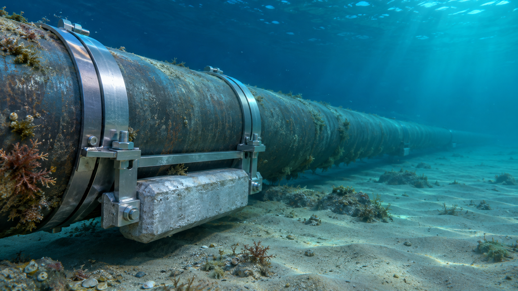
 Subsea Anode Retrofit Clamps: Sizing for Corrosion Protection LifeNov 06, 2026
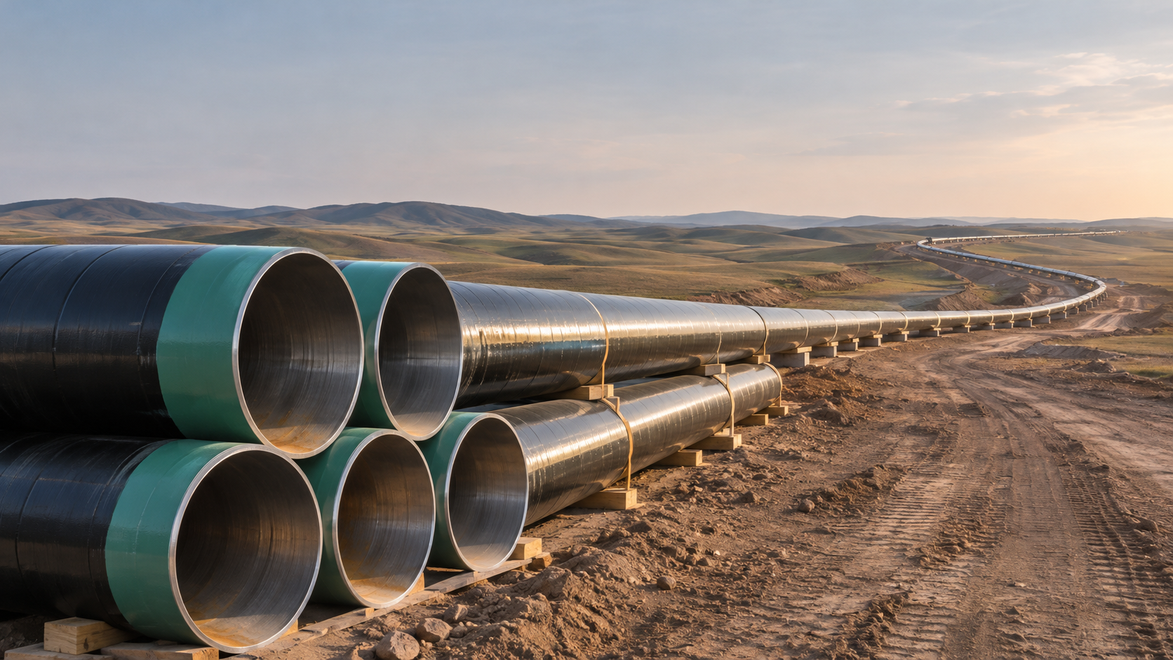
- Global Project Radar: Tracking Pipeline Projects From Bid to AwardNov 06, 2026
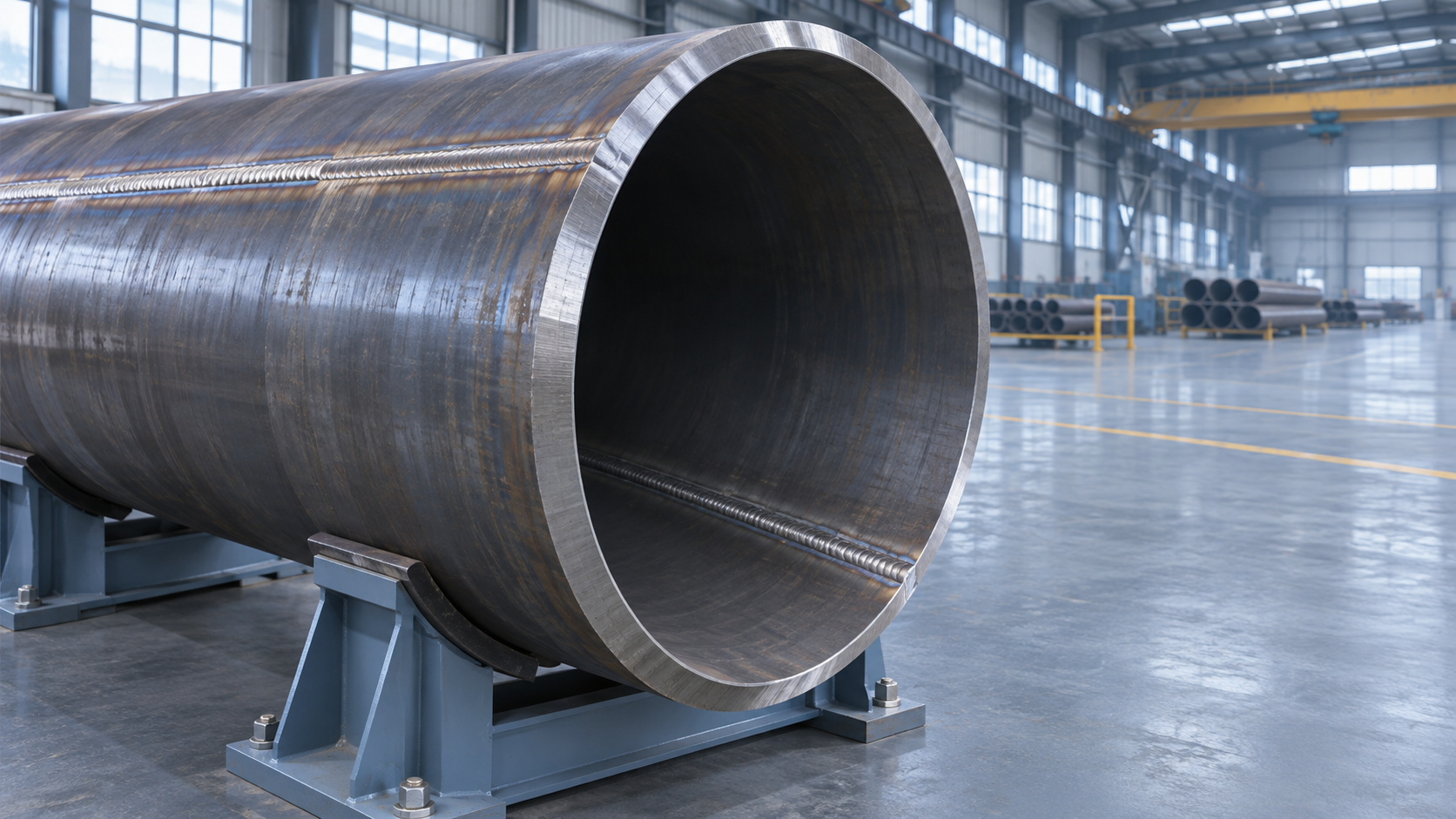
- High-Frequency Induction Welded Pipe: Weld Quality and Heat InputNov 06, 2026
- Double Submerged Arc Welded Pipe: What to Check Before OrderingNov 06, 2026

Weekly Insights
Stay ahead with our curated technology reports delivered every Monday.
Questions about pipe blasting or corrosion protection? Leave a message for technical insights from GPIC.
We respect your privacy. Your information is strictly confidential.
Recommended News