Global Pipeline Knowledge
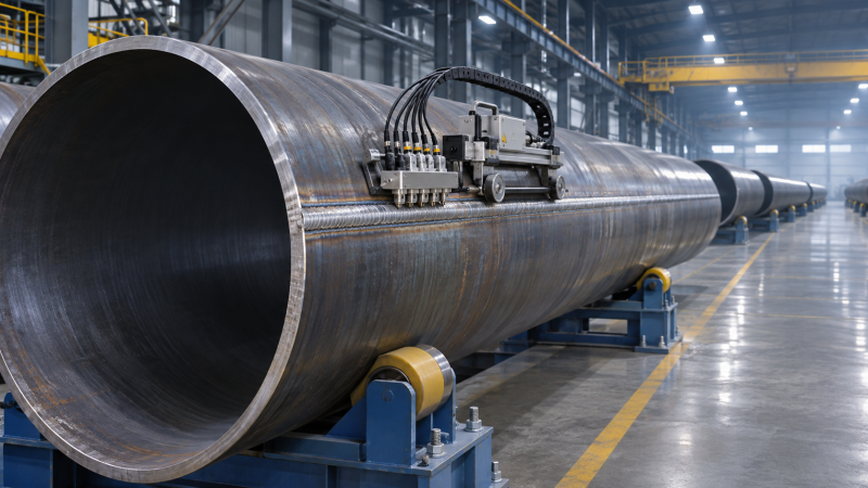
High-Frequency Induction Welded Pipe: Weld Quality and Heat Input
Weld quality in high-frequency induction welded pipe depends on whether the strip edges reach a suitable temperature and are forged together under controlled conditions. Electrical power alone cannot establish that result. Line speed, current distribution, edge geometry and squeeze-roll setting determine where energy is deposited, how long the edges are heated and whether contaminants are expelled from the joint.
A sound-looking seam therefore needs supporting evidence: stable production conditions, a suitable weld profile, mechanical and metallurgical test results, and nondestructive examination performed under the applicable pipe specification. A higher indicated heat input does not automatically produce a stronger weld; excessive heating can create defects or alter the heat-affected zone just as insufficient heating can leave an incomplete bond.
Where the heat goes
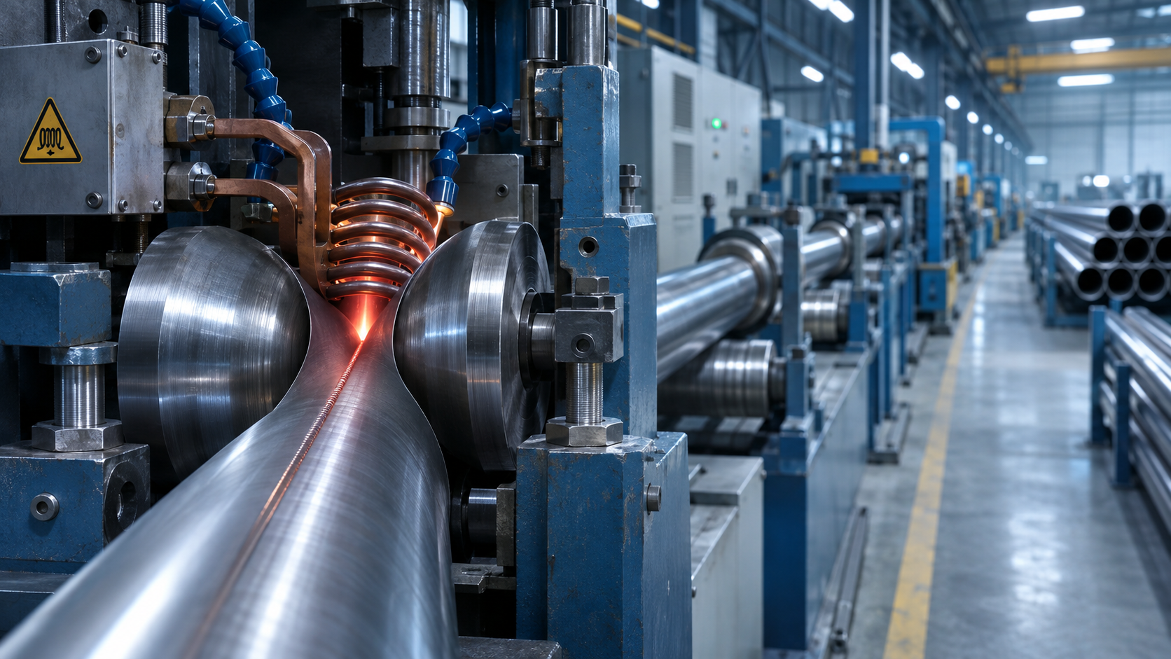
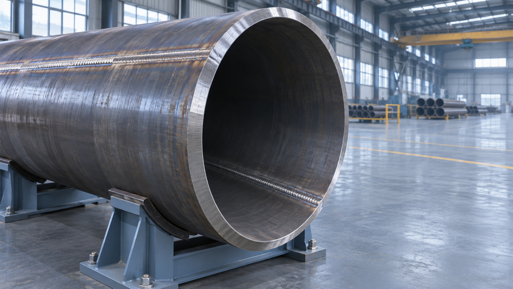
In high-frequency induction welding, a formed strip passes through an induction coil with its longitudinal edges separated by a narrow V-shaped opening. Induced current concentrates near the surface and along the facing edges. Resistance heating raises their temperature before squeeze rolls bring them together at the weld point. The edges are joined by pressure, with softened or molten material and surface contamination displaced into the internal and external weld beads.
The heating pattern is affected by frequency, coil position, the included angle and length of the open V, edge condition, tube geometry and the magnetic impeder arrangement inside the pipe where used. These variables influence electrical efficiency and the position of the hottest zone. A change in coil-to-strip spacing, for example, can alter the energy coupled into the work even when the power supply displays the same setting.
High-frequency current is concentrated near the surface, but its effective distribution also changes with temperature and magnetic properties. Consequently, the displayed frequency is not a direct measurement of temperature through the full wall thickness. Achieving adequate conditions at both the inside and outside edges becomes especially important when wall thickness or forming conditions change.
Heat input is a relationship, not a single setpoint
A simple power-to-line-speed ratio provides a useful indication of electrical energy supplied per unit length. It is not a direct measure of heat absorbed at the weld edges: power-supply losses, coil efficiency, current paths and the amount of heat conducted into the strip are not captured by that ratio alone. Values should be compared only when the measurement location, units and production configuration are understood.
If line speed increases while effective heating remains unchanged, the edges spend less time in the heating zone. The weld point can move, the edge temperature profile can change and the pressure stage may close a joint whose surfaces have not reached the intended condition. Increasing power may compensate, but the result must be verified through the qualified operating range and weld testing rather than assumed from the ratio.
Conversely, excessive effective heating can widen the heated region, destabilize the weld point or cause overheating and local expulsion of material. The visible bead may become irregular, but bead appearance alone cannot determine the internal condition. Changes to speed or power can also interact with squeeze-roll force: a hotter edge deforms more readily, so the same roll setting may produce a different upset and bead profile.
Meaningful production records link power, speed and frequency to the actual pipe size, wall thickness, steel grade and mill setup. A recorded setpoint without measured values, alarm limits or evidence of response to excursions gives limited insight into the welds produced.
Insufficient bonding and excessive heating
Insufficient bonding is associated with inadequate edge heating, poor contact under pressure, contaminated surfaces or an unstable weld point. The result can be a planar discontinuity along the bond line. A low-energy weld is a useful description of one process condition, but a similar lack-of-bond indication can arise from a mechanical or surface-preparation problem even when the electrical power reading appears normal.
Excessive local temperature introduces a different set of concerns. Overheating can coarsen the microstructure near the seam, while excessive expulsion can leave an unfavorable weld geometry or reduce local wall thickness. Oxide-related inclusions and hook-shaped features near the bond line can also impair properties; their formation is influenced by edge condition, heating and metal flow during upsetting. A metallographic section is needed to characterize such features, and its interpretation must follow the applicable acceptance criteria.
Neither a dark line in an etched macrosection nor a large flash bead is a standalone verdict. Etching response varies with material and preparation, and flash size reflects both thermal and mechanical conditions. The section must be interpreted alongside the bond-line geometry, continuity, microstructure and relevant test results.
Edge presentation and squeeze control
Strip edges must meet consistently across the wall. Edge mismatch, excessive waviness, poor slitting quality or unstable forming can prevent uniform pressure at the weld point. Misalignment may leave one surface adequately forged while the opposite surface has an unfavorable bond or bead. This is particularly relevant when a change in strip width, thickness or strength alters the way the tube enters the final forming stands.
Squeeze rolls provide the force that consolidates the heated edges and expels material. Too little effective squeeze can leave oxide or unbonded areas; excessive squeeze can create excessive upset, distort the seam or contribute to an unfavorable local profile. Roll position alone is an incomplete proxy for force because mill stiffness, roll wear and the resistance of the heated strip also affect the result.
Weld bead removal adds a separate control point. External and, where specified, internal trimming must remove the required flash without gouging the parent pipe or leaving unacceptable protrusion. A well-bonded seam can still fail dimensional or surface requirements if the scarfing tool is worn, misaligned or unstable.
Weld-zone heat treatment and properties
Some line-pipe specifications require treatment of the weld seam or the full pipe to achieve the specified properties. Seam heat treatment can modify the as-welded microstructure and reduce hard or brittle zones, but its effectiveness depends on temperature, heated width, alignment, cooling and verification against the specified condition. A treatment coil that is offset from the seam may leave part of the affected zone outside the intended thermal cycle.
The relevant property is not always tensile strength. A transverse tensile specimen may fracture away from the weld and satisfy a strength requirement while revealing little about the toughness of the bond line. Where required, flattening, guided-bend, impact, hardness or other tests address different aspects of weld performance. Their value depends on specimen location, orientation, temperature, acceptance criteria and whether the sample represents the pipe and production period under review.
Service conditions influence which evidence matters. Low-temperature service can make seam and heat-affected-zone toughness significant; sour-service requirements can introduce additional limits and testing for hardness or cracking resistance. These requirements must be stated in the applicable specification and purchase documents. A grade designation on its own does not establish a particular toughness test temperature or sour-service qualification.
Reading inspection results in context
Online electromagnetic or ultrasonic examination can detect specified longitudinal weld imperfections when the equipment, calibration, coverage and production conditions meet the governing requirements. A recorded pass applies to the examination performed; it does not establish that every possible flaw orientation, size or location was detectable. Coupling conditions, seam tracking, probe position, pipe geometry and inspection speed affect ultrasonic coverage, while each electromagnetic method has its own response limitations.
Examination before and after seam heat treatment does not answer exactly the same question. The timing determines which manufacturing stages are included in the inspected condition. Records should identify inspection position, calibration references, sensitivity verification, interruptions, alarm disposition and any re-examination after an intervention. An alarm is an indication requiring assessment under the procedure, not automatically a confirmed defect.
Hydrostatic testing provides evidence of pressure containment under the specified test conditions. It does not replace weld-zone toughness testing or qualified nondestructive examination, and a successful pressure test does not prove that a seam is free of subcritical discontinuities. Similarly, a satisfactory macrosection represents the sampled location; it cannot by itself demonstrate consistent weld quality over an entire production length.
Connecting mill evidence to the pipe requirement
API 5L is a commonly specified line-pipe standard, but its applicable edition, product specification level, manufacturing route and ordered supplementary requirements must be identified in the contract. Requirements differ with the specified product and service. Other governing standards or project specifications may apply, and a general description of high-frequency welding does not establish compliance with any particular edition.
Evidence is most useful when it can be traced from an individual pipe or production lot to its steel heat, manufacturing record, weld-seam treatment, inspection results and applicable test reports. The record should also make clear how pipe made during a process excursion was identified and dispositioned. A statement that the mill operated within its procedure is stronger when the procedure defines the permitted range and the production data show that the range was maintained.
Consider a change from a thinner wall to a thicker wall at the same outside diameter. Keeping the same nominal power-to-speed ratio does not establish equivalent welding conditions: edge heating through the thickness, forming response and required upset can all change. Relevant evidence would include the setup for the new wall, representative weld sections and the mechanical and inspection results required for that product. The acceptance decision rests on those documented results against the ordered requirements, not on similarity of a single mill setting.
Related Industries
Trending in Tech
 Subsea Anode Retrofit Clamps: Sizing for Corrosion Protection LifeNov 06, 2026
- Global Project Radar: Tracking Pipeline Projects From Bid to AwardNov 06, 2026
- High-Frequency Induction Welded Pipe: Weld Quality and Heat InputNov 06, 2026
- Double Submerged Arc Welded Pipe: What to Check Before OrderingNov 06, 2026
Weekly Insights
Stay ahead with our curated technology reports delivered every Monday.
Questions about pipe blasting or corrosion protection? Leave a message for technical insights from GPIC.
We respect your privacy. Your information is strictly confidential.
Recommended News