Global Pipeline Knowledge

Planning a Crack Detection Pig Run: Flow, Bends and Access
Planning a successful inspection run starts well before a tool enters the pipeline. For project managers, selecting Pipeline Crack Detection Pigs means confirming that operating flow, tool speed, bend geometry, bore restrictions, and launcher and receiver access are compatible with the proposed technology. The objective is not simply to get a tool through the line. It is to collect data that can support an integrity decision, without creating an unacceptable operational or recovery risk.
That distinction changes how the work should be scoped. A run may be mechanically feasible but deliver incomplete coverage because speed, debris or the inspection medium falls outside the tool’s requirements. Equally, a technically capable sensor cannot compensate for a trap that cannot safely accommodate the assembled tool.
Start with the threat, not the tool brochure
Before asking providers for a passage assessment, define the cracking threats the inspection is intended to address. Relevant concerns might include longitudinal seam anomalies, fatigue cracking, stress corrosion cracking or crack-like indications associated with girth welds. Their expected orientation, location and dimensions influence both technology selection and the way performance claims should be interpreted.
A tool advertised for crack detection is not automatically qualified for every crack type or orientation. Ask providers to identify the specific threats their proposed configuration is designed to detect, the conditions under which its detection and sizing performance were established, and any exclusions. A reported detection threshold should be considered alongside the associated probability of detection, confidence level, sizing tolerance and applicable feature population—not as a guarantee that every smaller feature will be found.
Conventional magnetic-flux-leakage inspection is commonly used for metal loss; a previous MFL run should not be treated as a substitute for a crack-focused inspection without evidence that its configuration addressed the relevant threat. Ultrasonic crack-detection tools and electromagnetic acoustic transducer tools are among the technologies that may be considered, but their suitability depends on the actual line, medium and inspection objective.
Build a line profile that providers can challenge
The most useful request for a technical assessment is more than a nominal diameter and total length. It is a reconciled picture of the pipeline from launcher to receiver, including changes and uncertainties. As-built drawings, operational records, previous inspection results and field verification may not agree; those discrepancies need owners and resolution dates.
The assessment package should identify pipe outside diameter, wall thickness and resulting internal diameter along the route, together with material and seam information where relevant. Include bend radii, bend angles and spacing; valves and their bore dimensions; tees, barred branches, reducers and fittings; elevation changes; and known dents or restrictions. Provide the operating medium, pressure and temperature ranges, flow scenarios and the condition of any lining or internal coating.
Pay particular attention to local changes. A nominally full-bore valve, for example, still needs its actual through-bore and opening condition checked against the proposed tool. A short thick-wall section may control the minimum internal diameter even when most of the line has ample clearance. When records are incomplete, the correct entry in the register is “unconfirmed,” not an assumed dimension.
Flow and speed: plan for the whole run
The provider needs an achievable tool-speed envelope, not just an average production rate. Flow can vary with demand, pump or compressor operation, elevation, pressure changes and operational interventions. Speed excursions may affect sensor response, positional data or coverage, even if the pig is eventually recovered.
Operations and the inspection provider should review the expected flow profile over the entire inspection window, including startup, shutdown and contingency conditions. In gas service, compressibility and changing pressure can make speed control particularly challenging. In liquid service, changes in flow rate and bore still matter. Tool bypass or speed-control systems may help where offered, but their effectiveness and operating limits need to be demonstrated for the specific line and duty.
The inspection medium is equally consequential. Many ultrasonic configurations require a suitable liquid coupling medium between sensors and the pipe wall. For a gas pipeline, that may mean evaluating a liquid batch or another compatible approach, with the associated separation, supply, handling and disposal arrangements. Electromagnetic acoustic transducer technology can operate without conventional liquid coupling, but it has its own tool-specific limitations. Neither option should be selected on medium compatibility alone.
Agree on actions before the run for a speed excursion, loss of flow or unexpected pressure differential. Identify who can change operating conditions, what information they will use and when the provider should be consulted. A control plan that depends on an unavailable pump, an unapproved flow reduction or a dispatcher who was not briefed is not yet a control plan.
Bends and restrictions: passage is a tool-specific calculation
A cleaning pig’s successful passage is useful evidence, but it does not prove that a longer, articulated inspection tool can negotiate the same line. Sensor carriers, seals, drive cups and connecting sections respond differently to tight bends, consecutive bends and changes in bore.
Give the provider bend radius, angle, orientation and separation, not simply a statement that the line contains standard bends. Closely spaced bends can impose a different articulation requirement from a single bend. The same applies to a restriction immediately before or after a bend, where the tool may not have room to realign.
A gauging run and, where appropriate, a geometry inspection can reduce uncertainty, but each has limits. A gauge plate may reveal evidence of a restriction without fully describing its shape or confirming passage of every inspection tool. Geometry data can provide a clearer picture of deformation, yet interpretation still depends on coverage and tool performance. The crack-tool provider should review the results against the actual tool assembly and document any remaining concerns.
If passage cannot be demonstrated, the project has choices: investigate the restriction, modify an accessible fitting, use a different qualified configuration, split the inspection into sections or assess an alternative inspection approach. The right answer depends on risk, access and the decision the data must support—not on preserving the original run date at all costs.
Launcher and receiver access can decide the schedule
Trap compatibility should be checked against the proposed tool’s assembled length, diameter, mass and handling requirements. Confirm barrel and closure dimensions, kicker and vent arrangements, valve bores, loading orientation and available space for assembly and extraction. A tool may fit inside the barrel but still be impractical to load because there is insufficient straight approach or lifting clearance.
The site review should also cover isolation, depressurization, draining, atmospheric hazards, lifting equipment and containment of the product or debris received. These controls must follow the operator’s procedures and applicable local requirements. For remote or offshore facilities, access windows, vessel or crane availability, and weather exposure can become critical path items.
Do not leave receiver planning until the launch is approved. Confirm how the tool will be detected on arrival, how the barrel will be isolated and made safe, and how the tool and any recovered material will be handled. If temporary equipment or modifications are needed, allocate engineering, approvals, procurement and testing time before committing to the inspection window.
Prepare the line for data quality, not just movement
Wax, scale, sediment and other deposits can interfere with sensor contact or coupling, restrict bypass, change tool speed and increase differential pressure. Cleaning requirements should therefore be agreed with the inspection provider and operations team rather than defined only by the number of cleaning runs.
A practical cleaning program specifies the sequence of tools, expected debris, monitoring arrangements, receiver capacity and criteria for deciding whether further cleaning is needed. Progress may be judged using recovered debris and operational observations, subject to the provider’s requirements. An aggressive cleaning approach is not automatically appropriate: the team must consider known restrictions, fragile equipment and the potential to accumulate debris ahead of a pig.
Preparation also includes tracking. Agree on pig signal locations, communications, estimated passage windows and procedures for investigating an unexpected delay. Establish a stuck-tool response before launch, including how its location would be narrowed down, who authorizes operational changes and what recovery options are credible. The plan should address both personnel safety and the consequences of interrupting service.
Define an acceptable result before mobilization
The scope should distinguish tool passage, usable data coverage and the ability to assess the target threat. Agree how the provider will report sensor performance, speed excursions, location accuracy, uninspected intervals and any degradation in detection or sizing capability. Also establish when preliminary findings will be communicated and how urgent indications will be escalated under the operator’s integrity procedures.
A reported indication is not the same as a confirmed defect. Depending on the threat and applicable assessment requirements, direct examination may be needed to verify its character and dimensions. Plan access, excavation or other examination resources with that possibility in mind, especially where obtaining permits or reaching the line takes significant time.
Commercial terms should make the consequences of incomplete data visible. If a section is missed because of flow, debris or a tool malfunction, identify how the cause will be determined and how rerun decisions, responsibilities and costs will be addressed. This is also the point to identify the standards, contractual requirements and local obligations applicable to the project, including their editions and scope, rather than assuming a provider’s generic specification covers them.
Make the go/no-go decision with a shared evidence record
Before mobilization, bring operations, integrity engineering, the inspection provider and site personnel together around the same unresolved-issues register. The key questions are concrete: Is the target threat within the tool’s stated capability? Are the minimum bore and bend configuration verified? Can flow and medium be maintained within the agreed limits? Are both traps ready? Is the cleaning evidence sufficient? Can the team respond to a stalled tool or an urgent finding?
Record the evidence behind each answer, the responsible owner and any conditional acceptance. Where a dimension or operating condition remains uncertain, state how it will be verified and what happens if it falls outside the approved envelope.
The planned Global Pipeline Integrity & Corrosion Portal takes this life-cycle view of pipeline decisions: tool capability matters, but so do the asset’s construction, operating environment, access and the quality of the evidence available. For a crack inspection project, the next useful step is a provider-reviewed line and operations package that makes those interfaces explicit before the run date is fixed.
Related Industries
Trending in Tech
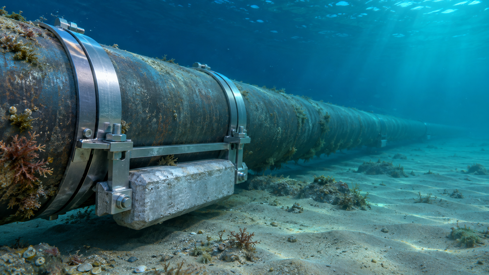
 Subsea Anode Retrofit Clamps: Sizing for Corrosion Protection LifeNov 06, 2026
- Global Project Radar: Tracking Pipeline Projects From Bid to AwardNov 06, 2026
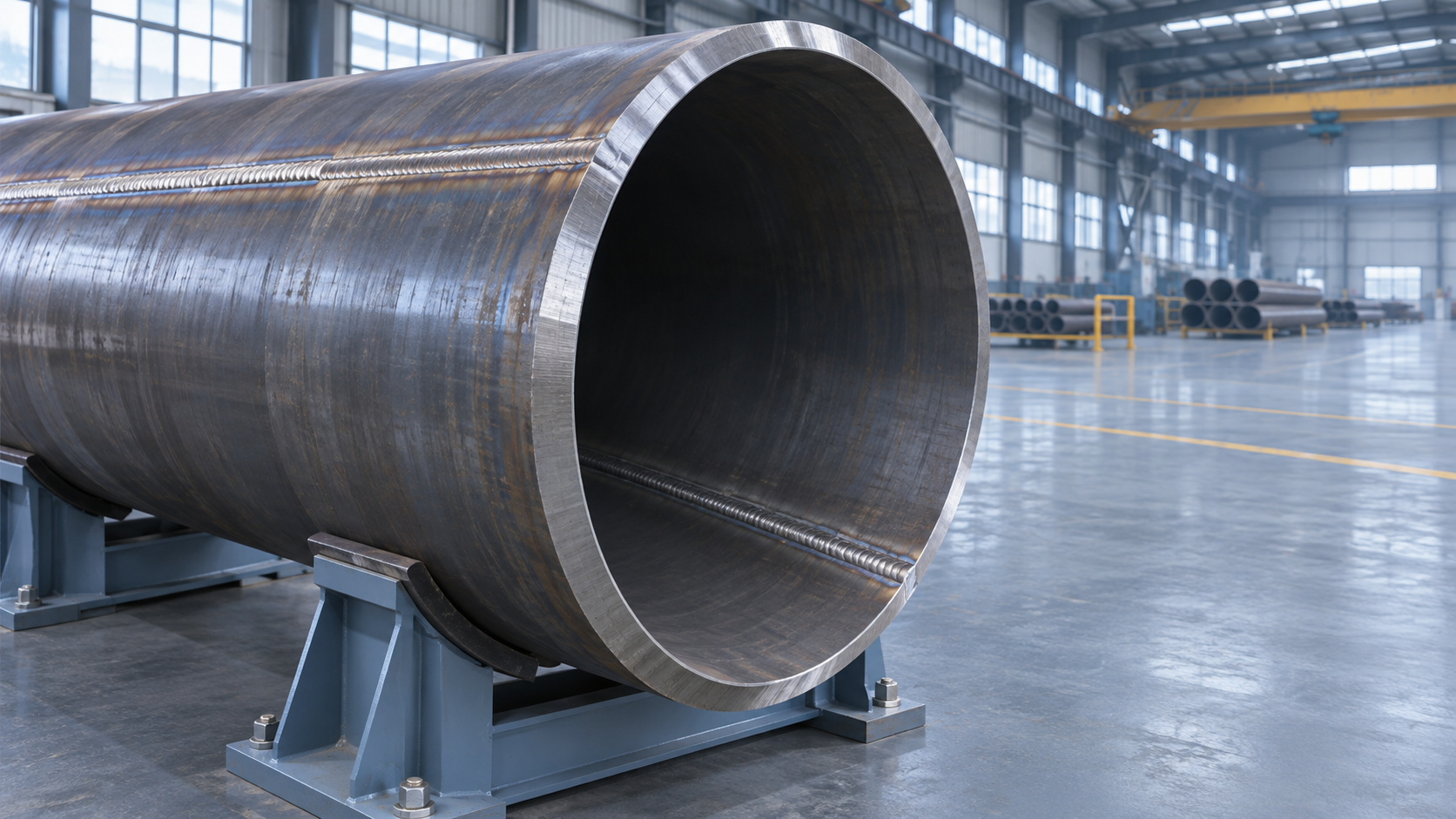
- High-Frequency Induction Welded Pipe: Weld Quality and Heat InputNov 06, 2026
- Double Submerged Arc Welded Pipe: What to Check Before OrderingNov 06, 2026


Weekly Insights
Stay ahead with our curated technology reports delivered every Monday.
Questions about pipe blasting or corrosion protection? Leave a message for technical insights from GPIC.
We respect your privacy. Your information is strictly confidential.
Recommended News