Global Pipeline Knowledge
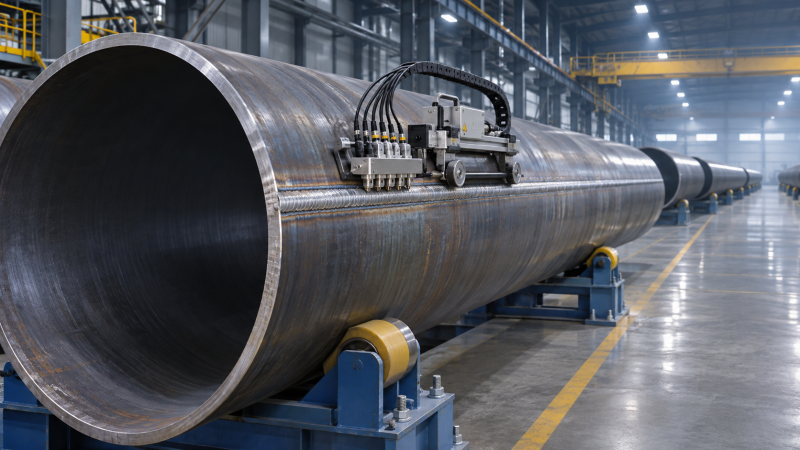
Pipeline Caliper Pigs: How They Detect Dents and Bore Restrictions
Pipeline caliper pigs detect changes in a pipeline’s internal shape by recording measurements as they travel through the bore. A dent pushes the pipe wall inward, while ovality changes the normally circular cross-section. Both alter the sensor readings and can indicate a restriction that affects flow, the passage of inspection tools, or the integrity of the pipe.
A caliper record does not establish the cause or severity of every feature on its own. Its value lies in locating and describing changes in geometry so that they can be compared with the pipeline design, construction records, other inspection data, and, where necessary, direct examination.
How a Caliper Pig Measures the Bore
A caliper pig is an instrumented tool propelled through a pipeline, commonly by the product or another fluid flowing in the line. Unlike a simple gauging plate, which gives a basic indication that it has encountered a restriction, a caliper tool records measurements along the route. The stored data is analyzed after the tool is recovered.
Many tools use articulated arms fitted with contact points or wheels that follow the internal surface. As an arm moves inward or outward, a sensor converts its position into a recorded measurement. Multiple arms distributed around the tool provide information about the bore at different circumferential positions. Other tool designs use non-contact measurement technologies or combine geometry measurements with additional sensors; their coverage and limitations depend on the equipment and operating conditions.
The tool also needs a way to relate each measurement to a position along the pipeline. An odometer commonly records travel distance, and some tools incorporate inertial sensors that help describe movement and orientation. Above-ground markers or known pipeline features can be used to correlate the recorded distance with the route. Distance errors accumulate, so the reported position of an anomaly is an estimate with an associated uncertainty, not an excavation coordinate by itself.
Measurements are interpreted against a reference bore. That reference may vary along the line because wall thickness, pipe dimensions, and components change. A smaller measured diameter is not automatically damage: it could correspond to a heavier-wall pipe section, a valve, or another designed feature.
What a Dent Looks Like in the Data
A dent is a localized inward deformation of the pipe wall. As a contact arm passes over it, the arm moves toward the tool’s center and then returns toward its previous position. Adjacent sensors can register the same feature at different times or amplitudes, allowing the analysis to estimate its axial length, circumferential extent, depth, and clock position.
The reported dent depth is generally expressed relative to a reference shape or diameter. That distinction matters: the measurement is not simply the difference between the largest and smallest readings at one location. The assumed reference, local ovality, tool centering, and the way the signal is processed all affect the result. A report should identify the sizing method and the uncertainty applicable to the feature.
Sensor spacing also matters. A narrow dent between contact points may be sampled poorly, particularly if its shape does not engage an arm near its deepest point. A wide, gradual deformation can be well represented by several arms, while a sharp or irregular feature poses a different measurement problem. The number of sensors alone does not establish performance; contact geometry, sampling, tool motion, and validated detection limits also matter.
Clock position describes where a feature lies around the pipe circumference, commonly using the top of the pipe as a reference. A reliable clock position requires suitable orientation information. Tool roll or uncertain orientation can reduce confidence in that position even when the axial location and the presence of a deformation are clear.
Ovality and Other Bore Restrictions
Ovality describes a departure from a circular cross-section. In a simplified measurement, it is often expressed using the difference between the maximum and minimum internal diameters relative to a stated reference diameter. The reference and calculation method must be clear before values from different reports are compared.
A dent and ovality can coexist. A locally flattened cross-section may contain a distinct inward indentation, and a tool that measures only a few directions may struggle to separate their contributions. Comparing the circumferential sensor pattern over a length of pipe helps distinguish a localized dent from a more extended change in shape.
Other features can reduce the available bore without being dents. Examples include a valve that does not fully open, an internal weld profile, a change in wall thickness, a liner, or material deposited inside the line. A contact sensor records the surface it encounters; it does not independently identify whether that surface is steel, a deposit, or an installed component. Non-contact tools have their own response to deposits and the fluid between the sensor and the wall.
Minimum diameter is useful for screening passage, but it is not the whole passage problem. A short restriction may be negotiated by one tool and stop another because of differences in body length, flexibility, sensor protrusion, or the distance between rigid sections. Bends near a restriction add another constraint. A clean caliper run therefore does not by itself prove that a larger or less flexible inspection tool will pass.
From Sensor Signals to a Reported Feature
Raw sensor readings contain more than pipe geometry. They also reflect the movement of the tool through bends, changes in speed, vibration, sensor response, and contact conditions. Processing aligns the measurements with distance, accounts for known tool behavior, and identifies patterns consistent with geometric features.
Analysts then compare indications with known pipeline components and available construction information. A repeatable diameter change at a recorded wall-thickness transition may be expected. An unexpected localized inward movement away from a known fitting warrants closer review. Matching the caliper trace to welds, valves, and markers can improve location confidence, but missing or inaccurate records can complicate that correlation.
A useful feature report states more than a single depth value. It should identify the estimated location, dimensions, orientation where available, classification, and applicable confidence or uncertainty. It should also distinguish measured geometry from interpretations about its cause. Calling a feature a suspected dent, for example, is different from confirming how it formed or whether the pipe wall is cracked.
Performance specifications need the same care. Detection concerns whether a feature is identified; sizing concerns how closely its dimensions are estimated. Both claims apply to defined feature types and test conditions. A stated sizing tolerance for a broad, smooth dent should not automatically be applied to a narrow feature at the edge of the tool’s detection capability.
Conditions That Affect Data Quality
Debris, wax, scale, or other internal deposits can prevent contact arms from following the pipe wall. The sensor may ride over material, stick, or return slowly after passing a feature. Cleaning before an inspection can improve contact, but cleaning requirements depend on the line and tool. A cleaning pig reaching the receiver is not proof that the bore is clean enough for every geometry sensor.
Speed affects how densely the wall is sampled along the pipeline and how well sensors respond to rapid changes. Excessive speed or rapid acceleration can impair the recording of short features; very low or uneven speed can introduce other difficulties, including tool movement that is difficult to interpret. The acceptable operating range is specific to the tool and should be considered alongside the expected flow conditions.
Tool wear and mechanical condition matter as well. Damaged arms, worn wheels, sensor faults, or restricted movement can leave gaps in coverage or distort measurements. Pre-run and post-run checks, together with the recorded channel status, help establish which sections of data are usable. A report should identify missing or degraded coverage instead of treating it as evidence that no anomaly is present.
Pressure and temperature can also influence both the measurement system and the pipe geometry. A dent under one operating pressure may have a different shape at another pressure, particularly if the deformation responds to pressure changes. Comparisons between inspection runs are stronger when operating conditions, reference methods, and tool capabilities are understood. An apparent change in depth alone does not establish that a dent has grown.
Interpreting a Restriction for Tool Passage
The critical passage dimension is the available internal profile along the route, not the nominal pipe diameter. The comparison should account for the reported restriction and its uncertainty, the dimensions of the proposed tool, and the tool’s ability to articulate through the surrounding pipe. A minimum-bore estimate based on incomplete sensor contact should be treated differently from a well-defined feature with good coverage.
A gauging plate is sometimes run ahead of an instrumented tool. If the plate returns undamaged, it offers evidence that a plate of that size passed under the conditions of that run. It does not map the restriction or prove that a long tool body, a sensor carrier, or a tool with different flexibility will pass. A damaged plate indicates an encounter with a restriction, but its deformation alone generally does not locate or fully characterize it.
When a caliper result suggests limited clearance, the next step may be a review of the raw data and component records, a further geometry run, or direct investigation. The appropriate response depends on the confidence in the measurement and the consequence of a tool becoming stuck. Debris removal will address some temporary restrictions; it will not restore the shape of a permanently deformed pipe.
When Geometry Needs Further Assessment
Dent depth alone does not establish structural significance. Location, shape, operating pressure cycles, and interaction with other features all influence the assessment. A dent associated with a weld, gouge, metal loss, or suspected cracking raises different questions from a smooth deformation in otherwise sound pipe. A geometry tool records shape; it does not reliably establish the presence or absence of all those accompanying conditions.
Correlation with metal-loss inspection, crack inspection, construction records, and previous geometry data can narrow the uncertainty, provided the datasets are aligned accurately. Where the evidence remains insufficient, excavation and direct examination may be needed to establish the surface condition and dimensions. The applicable assessment and response criteria should come from the relevant integrity program and governing requirements for the line, rather than from a universal dent-depth rule.
The most useful caliper result is therefore a traceable description of the bore, with its coverage and limits made visible. It supports a decision about passage or further assessment while leaving room for the additional evidence needed to determine the condition of the pipe.
Related Industries
Trending in Tech
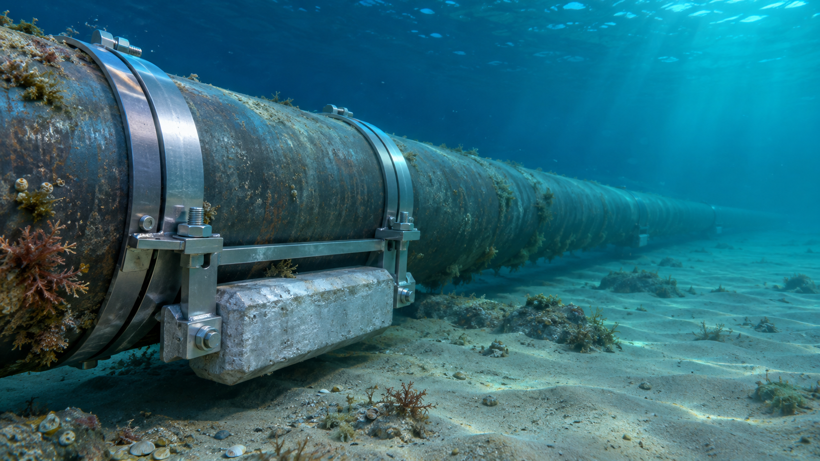
 Subsea Anode Retrofit Clamps: Sizing for Corrosion Protection LifeNov 06, 2026
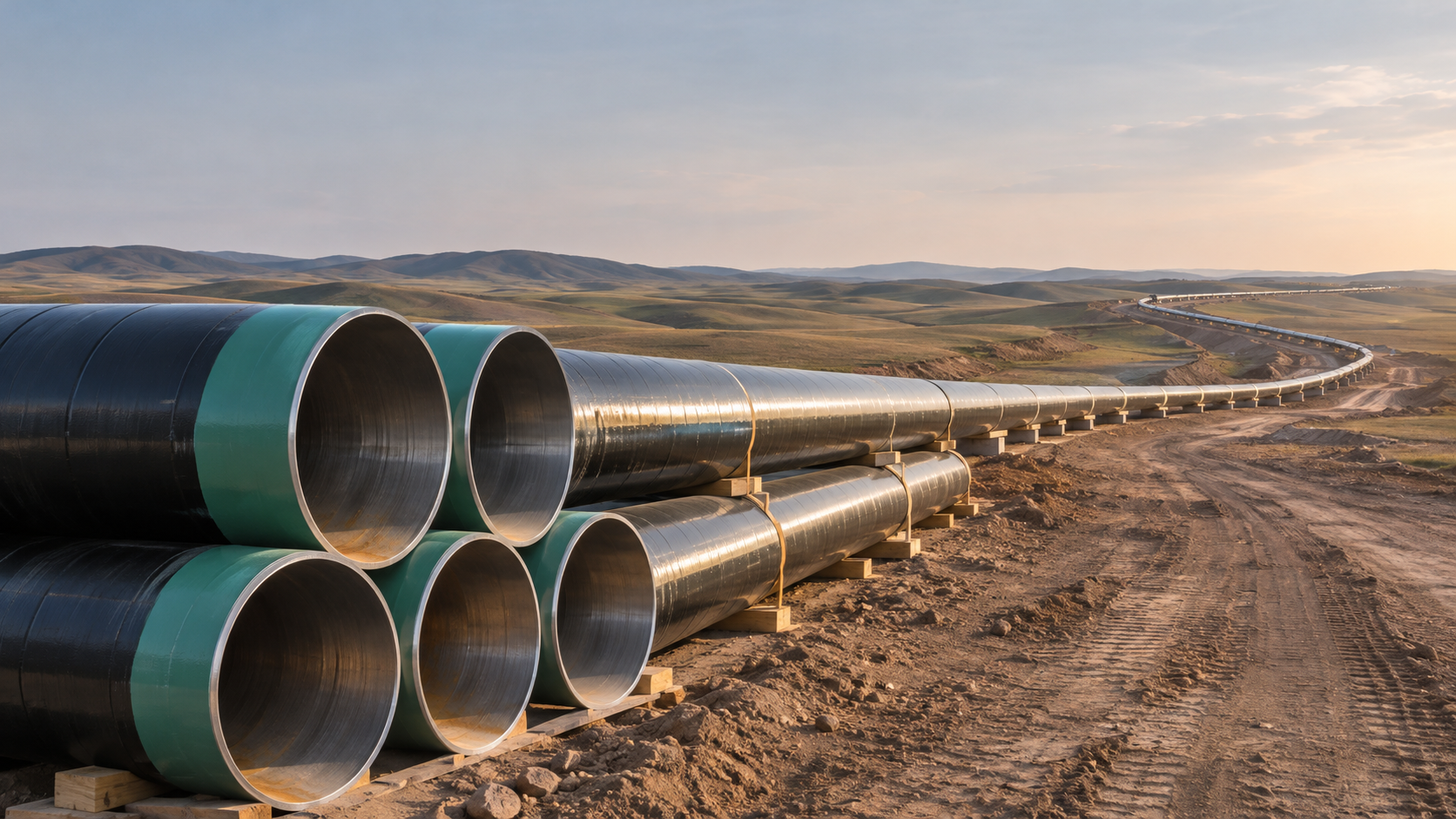
- Global Project Radar: Tracking Pipeline Projects From Bid to AwardNov 06, 2026
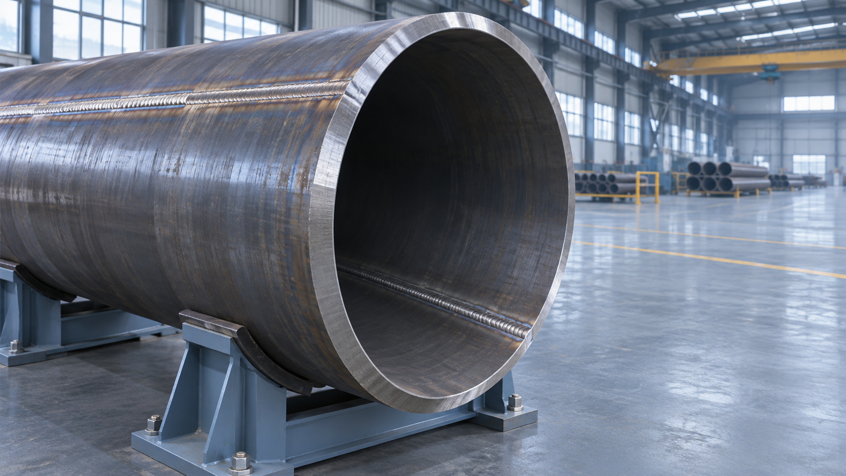
- High-Frequency Induction Welded Pipe: Weld Quality and Heat InputNov 06, 2026
- Double Submerged Arc Welded Pipe: What to Check Before OrderingNov 06, 2026

Weekly Insights
Stay ahead with our curated technology reports delivered every Monday.
Questions about pipe blasting or corrosion protection? Leave a message for technical insights from GPIC.
We respect your privacy. Your information is strictly confidential.
Recommended News