Two MFL inspection tools can report different signatures from the same pipeline feature. Sensor orientation may contribute, but magnetization direction and defect geometry often matter more.
For technical evaluators, the essential distinction is between the magnetic field applied to the pipe and the leakage-field components recorded by the sensors.
Reliable comparison also requires evidence about sensor coverage, lift-off, speed, wall thickness, and sizing algorithms under conditions representative of the pipeline being assessed.
This article explains those relationships and identifies the evidence needed to assess narrow axial or circumferential metal loss without relying on a single detection threshold.
What does “orientation” mean in an MFL tool specification?
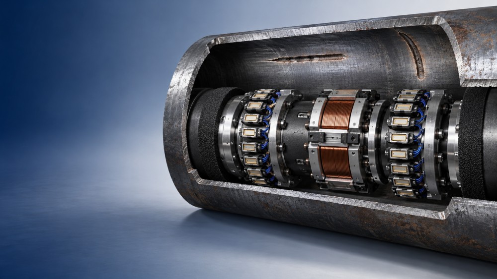
Orientation can describe three different things: magnetization direction, sensor measurement axes, or the physical arrangement of sensors. These distinctions directly affect how specifications should be interpreted.
Magnetization direction describes the principal magnetic flux direction within the pipe wall. Common configurations apply predominantly axial or circumferential magnetization, with different responses to elongated features.
Sensor measurement axes describe which components of the local magnetic field are measured. These are commonly expressed as axial, circumferential, and radial relative to the pipe.
Sensor arrangement describes where measurements occur, including circumferential spacing, axial offsets, and coverage around the pipe. Arrangement determines whether localized leakage fields are adequately sampled.
A radial sensing channel therefore does not mean radial magnetization. Likewise, a triaxial sensor does not establish that the tool magnetizes the pipe in multiple directions.
Ask suppliers to describe all three separately. A label such as “high-resolution MFL” provides insufficient information to establish directional sensitivity, coverage, or validated sizing capability.
Why magnetization direction matters for narrow metal loss
MFL tools magnetize the steel pipe wall. Where metal loss reduces the available magnetic path, some magnetic flux leaves the wall and creates a measurable leakage field.
The measured response depends on depth, width, length, profile, and orientation relative to the applied field. Peak amplitude alone cannot uniquely establish metal-loss depth.
As a general tendency, elongated metal loss that crosses the principal magnetization direction produces a more distinct disturbance than similar loss aligned with that direction.
This tendency helps explain directional sensitivity, but it is not a universal detection rule. Real corrosion has irregular edges, variable depth, and interacting pits.
Axial magnetization commonly provides useful sensitivity to circumferentially elongated metal loss. Very narrow axial features can present a harder inspection problem, depending on their geometry.
Circumferential magnetization is often selected to improve sensitivity to axially elongated metal loss. Narrow circumferential features require their own evidence under that configuration.
These relationships should guide qualification samples rather than substitute for testing. Feature width, depth, wall thickness, and actual magnetization conditions can substantially change the response.
Narrow corrosion must also be distinguished from cracking. Detection of an elongated metal-loss groove does not establish qualified performance for tight cracks or stress-corrosion cracking.
What do additional sensor axes actually improve?
Each sensor axis records a different projection of the leakage field. Changing the measurement axis changes the recorded signature without necessarily changing the underlying magnetization.
Radial measurements capture leakage normal to the wall, while axial and circumferential channels capture components along the surface. Their relative usefulness depends on feature geometry.
Multiple components can provide complementary information about feature boundaries, orientation, and signal shape. This can support classification and sizing when the interpretation method uses them effectively.
However, three measured axes do not automatically deliver three independent assessments of depth. Their signals arise from the same magnetic interaction and may share limitations.
Additional axes also cannot guarantee recovery of a feature that produces insufficient measurable leakage under the applied magnetization. Sensor sensitivity and background noise remain relevant.
Ask which channels contribute to detection, classification, and sizing. A channel displayed in analysis software may not contribute to every reported result or performance claim.
For a meaningful comparison, request examples showing what additional components resolve: improved feature separation, fewer classification errors, or better sizing within a defined defect population.
Can sensor spacing and operating conditions outweigh orientation?
Yes. Favorable magnetic orientation cannot compensate for inadequate spatial sampling or excessive sensor separation from the pipe wall. These effects must be evaluated together.
Circumferential sensor spacing determines how densely the tool samples around the pipe. Narrow features may fall between sensor paths or produce only limited lateral coverage.
Axial sampling depends on acquisition settings and tool speed. Where acquisition uses a fixed time rate, increasing speed increases the distance between successive measurements.
Nominal sensor pitch and nominal sampling interval therefore describe different dimensions. Neither alone establishes the smallest feature that the complete inspection system can reliably detect.
Lift-off is the separation between the sensing element and the inspected steel surface. Increasing lift-off generally weakens and spatially smooths the measured leakage signature.
Deposits, weld geometry, component wear, and sensor-carrier movement can change lift-off. Local changes may matter even when average tool speed remains within the specified range.
Wall thickness, steel magnetic properties, and magnetizer capability affect the magnetic state achieved during inspection. Performance demonstrated on thinner pipe cannot automatically establish equivalent capability elsewhere.
Velocity can also alter magnetic behavior and signal characteristics. Request the validated operating envelope, including how acceleration, speed excursions, and changing wall thickness affect results.
Which performance claims should technical evaluators compare?
Separate detection, identification, and sizing. A tool may detect an anomaly while misclassifying its cause or estimating its dimensions with uncertainty unsuitable for the intended assessment.
Probability of detection describes detection performance for a defined feature population under specified conditions. It should include the applicable confidence basis and qualification limitations.
Sizing accuracy describes agreement with reference dimensions, usually through an error tolerance and statistical coverage. It must identify which dimension and feature categories are covered.
A depth-based threshold alone is inadequate. Ten percent wall loss across a broad patch presents a different inspection problem from equally deep, very narrow corrosion.
Compare claims using a common feature definition and operating envelope. The following distinctions help expose specifications that appear equivalent but describe materially different capabilities.
Detection thresholds, reporting thresholds, and assessment thresholds serve different purposes. Confirm which threshold a supplier quotes and how unreported indications are handled during analysis.
What evidence should support a tool-selection decision?
Start with the corrosion morphology that matters to the pipeline. Historical excavations, previous inspections, service conditions, and corrosion mechanisms should shape the required feature population.
Request qualification results for narrow axial grooves, narrow circumferential grooves, isolated pits, and interacting corrosion where relevant. Include dimensions that challenge the proposed configuration.
Artificial defects provide controlled geometry and repeatable comparisons, but simplified shapes may not reproduce natural corrosion. Strong evidence combines controlled testing with representative field validation.
Reference measurements also carry uncertainty. Ask how depth and dimensions were established, how spatial alignment was performed, and whether the reference method resolved narrow features.
Where practical, use blind trials in which analysts do not know defect locations or dimensions. Include missed features and false calls alongside successful detections.
Review sample sizes within each important feature class. Strong aggregate performance can conceal weak evidence for the narrow defects that drive the purchasing decision.
If two configurations claim different benefits, request matched comparisons using the same defects and comparable conditions. Otherwise, apparent improvement may reflect different qualification populations.
The deliverable should connect each performance claim to its supporting evidence and limitations. Brochure terminology becomes useful only when evaluators can trace it to demonstrated results.
How should conflicting indications from two tools be investigated?
Suppose an axially magnetized tool reports a weak, elongated indication, while a circumferentially magnetized tool reports a clearer axial feature at the same location.
That difference is consistent with directional sensitivity, but it does not prove orientation caused the discrepancy. First confirm that both datasets describe the same feature.
Check positional alignment, run dates, wall thickness, speed, sensor coverage, and lift-off indicators. Differences in reporting rules or feature grouping can also change apparent results.
Then compare available field components and interpretation methods. A different sizing model may explain different reported depths even where the underlying signal evidence is similar.
If the discrepancy affects an integrity decision, select a suitable verification method and document its uncertainty. Field measurements should resolve the disputed dimensions wherever practicable.
For repeat inspections, account for changes in tool configuration and analysis methodology before calculating corrosion growth. A larger reported depth does not alone establish actual growth.
Choose MFL inspection tools by demonstrated performance for relevant defects
Sensor orientation matters because it determines which leakage-field components are recorded. Magnetization direction matters because it influences the magnetic response generated by the defect itself.
The practical decision also depends on sampling, lift-off, operating conditions, and interpretation. No single axis count, resolution label, or depth threshold captures that combined performance.
Select the configuration with credible evidence for your pipeline’s expected corrosion geometry and inspection conditions. Specify complementary inspection or verification where important uncertainties remain unresolved.
A defensible evaluation ends with traceable performance requirements, representative qualification evidence, and clear acceptance criteria. Those provide a stronger purchasing basis than general claims of superior detection.