Global Pipeline Knowledge
Ultrasonic vs EMAT Crack Detection Pigs: Key Selection Criteria
For a liquid pipeline, a conventional ultrasonic crack detection pig is often a practical starting point because the transported liquid can provide the acoustic coupling needed to inspect the pipe wall. For a gas pipeline, an electromagnetic acoustic transducer (EMAT) tool may avoid the need to introduce a liquid couplant. Neither choice follows from the operating medium alone: the selected tool must also detect the cracks of concern, negotiate the line, and deliver usable data under the conditions of the run.
The most useful comparison of Pipeline Crack Detection Pigs therefore starts with the integrity question, not a technology label. An operator looking for axial stress corrosion cracking in a transmission line, for example, needs a different performance demonstration from one concerned about cracks near girth welds. In both cases, the ability to run a tool through the line is only the beginning; the inspection must produce evidence that supports the intended assessment and subsequent decisions.
Where Ultrasonic and EMAT Tools Differ
Conventional ultrasonic inspection uses transducers to introduce sound into the pipe wall and interpret returning signals. Crack inspection tools commonly use angled sound paths so that the beam interacts with features oriented unfavorably for a straight-through measurement. A liquid coupling path is needed between the transducer and the pipe wall. In a liquid pipeline, the product may provide that path, provided its properties and condition are suitable for the tool. Gas lines can sometimes be inspected with ultrasonic tools using a liquid batch, but the added operating arrangements must be assessed.
EMAT tools generate and receive ultrasonic waves electromagnetically in the pipe wall, without requiring a liquid couplant at the sensor-to-wall interface. This can make EMAT attractive for gas service, where maintaining a liquid coupling path may be difficult or disruptive. It does not mean that the inspection is independent of surface condition, tool position or pipe properties. Sensor lift-off, deposits, material characteristics and the design of the particular tool can all influence the signals obtained.
These are technology-level distinctions, not a ranking of individual tools. Two tools using the same principle can have different sensor coverage, reporting thresholds and demonstrated performance. Compare the proposed tool configurations and their evidence, rather than assuming that the name of the method defines the result.
Start With the Crack Threat and the Decision It Must Support
Define the expected crack orientation, location and morphology before requesting performance figures. Relevant threats may include stress corrosion cracking, fatigue cracks, cracks associated with longitudinal seams or manufacturing features, and defects near welds. The inspection objective should specify whether the concern is an axial, circumferential or differently oriented feature, and whether the relevant surface is internal, external or either.
Orientation matters because a sensor arrangement designed for one direction may not have equivalent sensitivity in another. An axial crack detection tool should not automatically be assumed to provide adequate coverage for circumferential cracks. Similarly, a tool capable of detecting an isolated crack may not characterize a closely spaced crack colony in the same way. Weld geometry and nearby features can also complicate interpretation.
The required output matters just as much as the threat description. A screening run intended to identify locations for excavation has different demands from an assessment that depends on estimated crack depth. Ask whether the proposed service reports location, orientation, length and depth, and how its stated sizing uncertainty applies to the defects of interest. A depth estimate with uncertainty that is too large for the planned engineering assessment may trigger unnecessary excavation or leave an unacceptable decision margin.
For an asset with incomplete history, the threat definition may need to draw on pipe manufacturing records, seam type, operating history, prior inspections, failures on comparable assets and corrosion or coating information. Missing information is itself a planning input: it may justify a broader examination strategy or targeted follow-up, rather than an unsupported assumption that only one crack type is present.
Check the Operating Medium and the Cost of Making the Run Possible
In a liquid line, confirm that the proposed ultrasonic tool can operate with the actual product and its expected temperature and condition. Entrained gas, deposits or other conditions that interrupt the coupling path can degrade data. The inspection provider should explain how coupling quality is monitored, how affected sections are identified and what happens when coverage falls below the agreed requirement.
In a gas line, EMAT can remove the need for a liquid coupling batch, but it still needs a viable operating envelope. The tool must be compatible with the line’s pressure, temperature, flow and gas conditions, as well as the available launch and receive arrangements. An EMAT run is not automatically the simplest option if the available tool cannot negotiate the asset or demonstrate the required crack performance.
A liquid-batch ultrasonic run may be worth considering where the desired performance is available and the operating plan supports it. The comparison should include sourcing and introducing the liquid, maintaining the batch during the run, product separation, receiving and disposal or handling, and any operating interruption. Batch management is also a data-quality issue: a run that loses the necessary coupling may require another inspection or leave sections without the intended evidence.
Compare the full inspection program, including preparation and follow-up, rather than the quoted run price alone. A technically suitable approach can become a poor choice if its operating requirements cannot be maintained throughout the line.
Establish Whether the Tool Can Run and Inspect the Whole Line
Tool passage and inspection coverage are related but separate questions. A cleaning pig that passes through a pipeline does not establish that a longer, instrumented crack tool can negotiate the same route or maintain sensor contact and positioning. Provide prospective vendors with line drawings and operating data, then resolve discrepancies in the physical configuration before committing to a run.
The review should address internal diameter and wall-thickness changes, bends and bend spacing, valves, tees, bore restrictions, fittings, elevation changes, and launcher and receiver dimensions. Confirm the actual tool configuration offered for the job, including its overall length and any speed-control equipment. A tool may be available for the nominal diameter yet still be unsuitable for a particular combination of features.
Flow and speed deserve attention throughout the route, not just at the inlet. Speed excursions can affect data acquisition and interpretation, while insufficient flow may create passage risks. The vendor should identify the acceptable speed range for the offered configuration, how speed will be monitored, and the effect of excursions on coverage and performance. Account for operating changes that may be needed to keep the tool within that range.
Cleaning is also part of the inspection design. Debris, wax, scale or uneven internal conditions can interfere with sensor positioning, coupling or signal quality, depending on the method. Agree on the cleaning objective and how readiness will be judged; a cleaning program that moves material without achieving an inspectable surface may not support the intended crack survey.
Read Performance Claims Against the Pipeline, Not in Isolation
A detection claim is useful only when its conditions resemble the job. Request the performance specification for the exact tool and sensor configuration, including the defect types, dimensions, orientations and locations to which it applies. Ask for the associated probability of detection, false-call considerations and sizing tolerances, together with the conditions and confidence terms used to state them.
Examine how the performance was established. Representative validation considers factors such as wall thickness, pipe material, seam or weld configuration, surface condition, tool speed and the shape of the features. A result demonstrated on one set of artificial reflectors or pipe samples should not automatically be treated as equivalent to performance on tight, irregular cracks or crack colonies in the subject line. Field excavation comparisons can add useful evidence, but their value depends on the quality of the direct measurements and whether the examined features represent the population of interest.
Separate detection, identification and sizing. Detecting a signal does not necessarily mean the tool can reliably distinguish a crack from another feature, and identifying a crack-like indication does not guarantee a depth estimate suitable for every assessment. Ask how the provider handles ambiguous indications, interacting features and indications near seams or welds.
Also define the reporting threshold and its consequences. Features below that threshold may not be reported even if they exist, while data quality restrictions can make the practical sensitivity worse in particular sections. An inspection report should allow the operator to distinguish between a surveyed section with no reportable indications and a section where the required inspection sensitivity was not achieved.
Make Data Coverage and Follow-Up Part of the Purchase
The scope should state what constitutes an acceptable run, not merely require the tool to reach the receiver. Specify the required inspection coverage, the data-quality checks, how missed or degraded areas will be reported, and the process for deciding whether a rerun or alternative examination is needed. Coverage should address the relevant pipe wall and crack orientations, not just the distance travelled.
Request deliverables that support subsequent work: feature locations referenced to usable pipeline markers, descriptions of indications, sizing estimates where applicable, uncertainty, and a clear record of limitations. Agree how the provider will communicate urgent or significant findings, and how final data and interpretation will be transferred for the operator’s integrity assessment.
An in-line inspection indication is not a confirmed defect. Plan direct examination at selected locations using methods appropriate to the suspected feature and the surface being examined. Excavation findings can confirm classification and dimensions, support repair decisions and improve interpretation of the wider dataset. The validation plan should consider both significant reported indications and the need to understand false calls or missed features where practicable.
Before awarding the work, compare each proposal against the same asset-specific threat statement and operating envelope. If conventional ultrasonic and EMAT options both meet the required performance, the deciding factors may be run preparation, coverage confidence, disruption and the quality of follow-up support. If neither can demonstrate adequate coverage for the threat, change the inspection strategy rather than treating a completed run as proof that the pipeline is free of cracks.
Related Industries
Trending in Tech
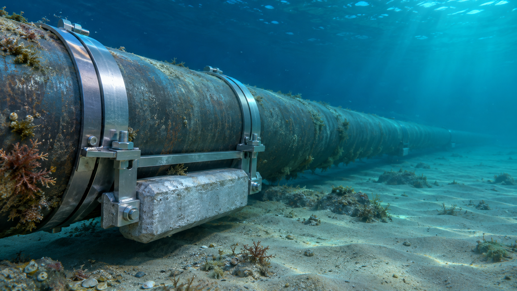
 Subsea Anode Retrofit Clamps: Sizing for Corrosion Protection LifeNov 06, 2026
- Global Project Radar: Tracking Pipeline Projects From Bid to AwardNov 06, 2026
- High-Frequency Induction Welded Pipe: Weld Quality and Heat InputNov 06, 2026
- Double Submerged Arc Welded Pipe: What to Check Before OrderingNov 06, 2026

Weekly Insights
Stay ahead with our curated technology reports delivered every Monday.
Questions about pipe blasting or corrosion protection? Leave a message for technical insights from GPIC.
We respect your privacy. Your information is strictly confidential.
Recommended News