Global Pipeline Knowledge
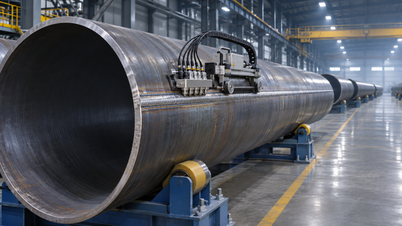
How Pipeline Crack Detection Pigs Find Longitudinal Cracks
Longitudinal cracks can threaten pipeline integrity, but finding them requires inspection tools suited to their orientation and the pipeline’s operating conditions. Pipeline Crack Detection Pigs use technologies such as ultrasonic testing to identify potential crack-like indications along the pipe wall. Their findings are not automatically confirmed defects: detection and sizing have limits, and an indication may need further assessment or direct examination before an operator can decide what it means.
The distinction matters because a crack can be narrow, difficult to distinguish from other features, and more consequential than its surface appearance suggests. A useful inspection is therefore more than a tool run. It depends on selecting a method for the expected threat, getting the sensors through the line under suitable conditions, and understanding what the resulting data can—and cannot—support.
Why longitudinal cracks need a particular inspection approach
A longitudinal crack runs generally along the length of a pipeline. It may occur in the pipe body, at or near a longitudinal seam weld, or as part of a group of closely spaced cracks. Depending on the asset, relevant threats can include stress corrosion cracking, fatigue-related cracking and manufacturing-related seam features. These mechanisms do not all look alike, and a tool’s ability to detect one type should not be assumed for another.
Internal pressure produces circumferential, or hoop, stress in the pipe wall. That stress can open an axial crack, making its depth, length and interaction with nearby features relevant to an integrity assessment. Pressure history, material properties, wall thickness and toughness also matter. A long indication is not automatically more urgent than a shorter one; the assessment depends on the available dimensions, their uncertainty and the loading conditions.
Orientation also affects inspection. Sensors must interrogate the wall in a way that produces a useful response from the expected crack plane. A tool configured for axial features does not necessarily have the same performance for circumferential cracks, which run around the pipe. Before comparing technologies, the operator needs to define which direction and location of cracking are of concern.
How an ultrasonic crack detection pig sees the pipe wall
An ultrasonic crack detection pig travels through the pipeline carrying transducers arranged around its circumference. The transducers introduce sound into the pipe wall and record returning signals. For longitudinal cracks, a typical approach directs angled ultrasonic beams so that they travel around the circumference of the pipe wall and interact with surfaces approximately aligned with the pipeline axis.
When a beam encounters a crack-like feature, part of its energy can reflect back toward a sensor. The tool records the response together with information used to locate it along the line and around the pipe circumference. Analysts then interpret the signals, often alongside weld locations, geometry information and other inspection records.
That description is deliberately simpler than the actual signal analysis. A response can be influenced by crack orientation, surface roughness, branching, nearby weld geometry and the sensor’s position. The analyst is not looking at a photograph of a crack. The report is an interpretation of measured signals, supported by the tool’s performance information and whatever validation data are available.
Conventional piezoelectric ultrasonic tools generally need a liquid coupling path between the transducer and the steel. A liquid pipeline may provide suitable coupling, subject to the tool and product conditions. In a gas line, an operator may consider a liquid batch or another inspection technology, but introducing and managing a liquid batch is an operational decision in its own right. Product compatibility, separation, handling and recovery all need to be addressed; it is not simply a matter of choosing the most sensitive sensor.
Other methods—and why a metal-loss run is not enough
Electromagnetic acoustic transducer, or EMAT, tools generate and receive ultrasound using electromagnetic principles and do not require the same liquid coupling path as conventional piezoelectric ultrasonic tools. They can therefore be considered for some gas-pipeline applications. Their suitability still depends on the particular tool, pipeline and threat: coupling is only one part of the inspection problem. Surface conditions, lift-off, wall properties, speed and sensor coverage can affect the data.
Some magnetic inspection configurations are also designed to respond to axial crack-like features. Their capabilities should be checked against the actual target population rather than inferred from the word “magnetic.” Standard magnetic-flux-leakage inspection is widely used for metal-loss assessment, but a metal-loss tool should not be treated as a substitute for a qualified crack inspection merely because it has passed through the same line.
That is a common source of false reassurance. A previous inspection may have produced a useful corrosion baseline while providing limited evidence about tight longitudinal cracks. Conversely, a crack-focused run does not necessarily replace the metal-loss, geometry or mapping information needed for a broader integrity program. The reports and performance specifications need to be read for their stated purposes.
What determines whether a crack is detected and sized?
The first question is not just whether a provider offers crack detection. It is whether the stated performance applies to the features and conditions in the line being inspected. A shallow, isolated feature away from a weld can present a different problem from a crack colony or a feature interacting with a seam.
Detection capability and sizing capability should be considered separately. A tool may detect a feature without measuring its depth with enough confidence for a particular assessment. Published performance may be expressed in terms of probability of detection, classification or sizing tolerance, but those claims have boundaries. Ask what defect types, dimensions, orientations, wall thicknesses and test conditions underpin them, and whether the claim applies to the full line or only to qualified portions.
In practice, several conditions can make the data harder to interpret:
- Crack morphology: Branching, tight faces, clusters and irregular depth can produce responses that differ from a simple individual crack.
- Location: Longitudinal seam welds and nearby geometric changes can complicate both detection and classification.
- Internal condition: Deposits, debris or roughness may interfere with sensor contact, coupling or signal quality, depending on the technology.
- Tool behavior: Excessive speed, speed variation, sensor lift-off or lost channels can reduce usable coverage.
- Pipe properties: Changes in wall thickness, diameter or material can affect signal behavior and the applicability of a performance claim.
Coverage is as important as the headline specification. A report should identify where the tool collected adequate data, where sensors were impaired and where the provider cannot make the normal performance claim. “No reportable indications” in a well-inspected section is not the same statement as “no cracks anywhere in the pipeline.”
Getting a tool through the line is part of the inspection
A successful cleaning-pig run is useful preparation, but it does not prove that an instrumented crack tool can negotiate the line. Crack detection pigs can have different lengths, sensor assemblies, bypass arrangements and bend limitations. Launcher and receiver dimensions, valve openings, bore restrictions, fittings and changes in diameter all need to be checked against the specific tool.
Flow also deserves attention. Too little flow may prevent a stable run; too much or highly variable flow may take the tool outside its qualified operating envelope. In gas service, speed control can be particularly relevant where pressure and flow conditions change along the route. The practical question is not only “Can the pig reach the receiver?” but “Can it collect interpretable data while doing so?”
Cleaning requirements depend on the technology and what is in the line. An operator may need several preparation runs, evidence from debris recovery, or an agreed cleanliness criterion before the inspection proceeds. For an offshore line with limited intervention access, preparation and contingency planning may carry different weight than for an accessible onshore segment. Neither setting makes a poor-quality data set acceptable; it changes the cost and feasibility of doing the run again.
From an indication to an integrity decision
After the run, the provider typically processes the measurements and issues a report identifying reportable features, locations, estimated dimensions, classifications and relevant data limitations. An indication is a signal interpreted as a possible feature. A confirmed defect is a separate determination made using applicable acceptance criteria and evidence. The terminology in the contract and report should make that distinction clear.
The operator then considers the findings alongside pressure history, pipe and seam records, material properties, earlier inspections, leak or failure history, and the consequences of a failure at the location. A reported depth estimate should not be used as though it were an exact measurement. Its uncertainty, the possibility of interacting cracks and the quality of the surrounding data can change the assessment.
Where warranted, direct examination may involve excavation or other access, surface preparation and suitable nondestructive examination. Field measurements can help confirm the nature and dimensions of a feature and inform repair decisions. They can also provide feedback on the in-line inspection performance, provided the field findings and locations are documented carefully. Not every indication can or should be excavated; selection depends on risk, assessment results, access and applicable requirements.
Reassessment planning should also account for the mechanism. A comparison with an earlier run may help, but apparent changes can reflect different tools, reporting thresholds, feature matching or sizing uncertainty rather than growth alone. If the earlier inspection was not qualified for the same threat, it may be a poor baseline for that comparison.
Questions to ask before relying on a crack inspection
A useful starting point is to ask the inspection provider to connect its specification to the actual pipeline: Which axial threats and seam types are covered? What are the detection, classification and sizing limits, and under what validation conditions were they established? What speed range, cleanliness, coupling and sensor coverage are required? How will reduced coverage or anomalous data be reported?
The answers should be reviewed with operations and integrity personnel, not only against a tool brochure. Confirm the applicable project requirements, regulatory obligations and assessment methods for the jurisdiction and asset, including the relevant editions where standards are invoked. A planned resource such as the Global Pipeline Integrity & Corrosion Portal (GPIC) is intended to put those decisions in the context of the whole asset—from pipe manufacture and coatings to inspection access and repair.
For a reader evaluating a completed run, the most revealing pages may be the limitations and coverage sections, not the indication count. They show where the inspection provides evidence, where uncertainty remains, and where another method or direct examination may be needed before an integrity decision is defensible.
Related Industries
Trending in Tech
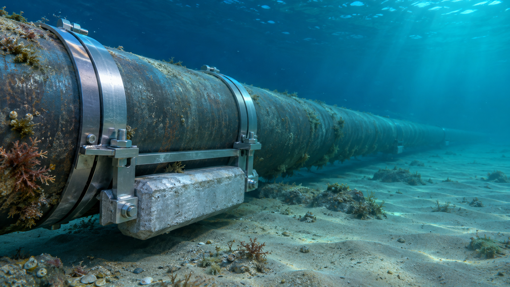
 Subsea Anode Retrofit Clamps: Sizing for Corrosion Protection LifeNov 06, 2026
- Global Project Radar: Tracking Pipeline Projects From Bid to AwardNov 06, 2026
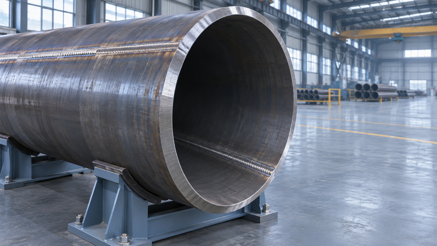
- High-Frequency Induction Welded Pipe: Weld Quality and Heat InputNov 06, 2026
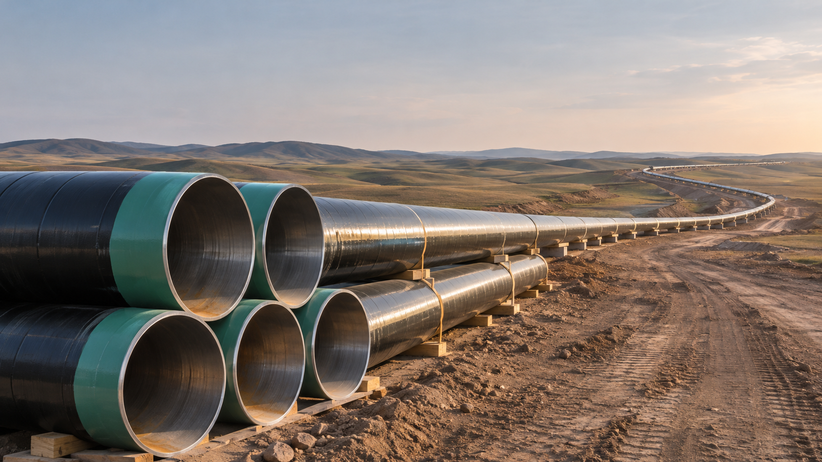
- Double Submerged Arc Welded Pipe: What to Check Before OrderingNov 06, 2026

Weekly Insights
Stay ahead with our curated technology reports delivered every Monday.
Questions about pipe blasting or corrosion protection? Leave a message for technical insights from GPIC.
We respect your privacy. Your information is strictly confidential.
Recommended News