Global Pipeline Knowledge
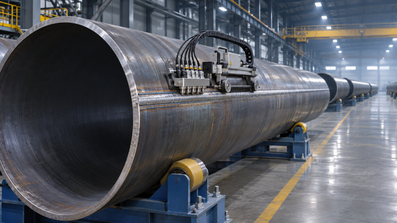
Selecting a Cathodic Protection Tester: Accuracy, Impedance and Range
Selecting a Cathodic Protection Tester: Accuracy, Impedance and Range
Selecting Cathodic Protection Potential Testers requires more than comparing advertised voltage ranges. Measurement accuracy, input impedance, resolution, and resistance to electrical interference can all affect the reliability of pipeline potential readings in the field. For technical evaluators, the right choice depends on the reference electrode, measurement method, site conditions, and applicable protection criteria. This guide examines the specifications that matter, the questions to ask suppliers, and the limitations to consider when comparing instruments for pipeline integrity work.
The most useful starting point is not the instrument catalogue. It is the measurement the crew must make: a routine pipe-to-soil reading at an accessible test post, an interrupted-current survey along a transmission line, or a subsea measurement using a remote electrode. Each places different demands on the meter, the electrode and the way the result is recorded.
Start with the measurement, not the display
A pipeline potential is a voltage measured between the structure and a reference electrode in the surrounding electrolyte. On land, a copper/copper sulfate reference electrode is commonly used in soil; offshore work often uses a suitable silver/silver chloride electrode in seawater. The electrode type must accompany the reading because potential values are meaningful only with their reference and measurement conditions.
Decide whether the instrument will record a steady “on” potential, an instant-off potential, a depolarization response, or data from a close-interval potential survey. A meter that gives a stable reading at a test post may not capture the brief period needed for an interrupted-current measurement. Likewise, a logger with fast sampling is not automatically suitable for every close-interval survey if synchronization, positioning or data storage is inadequate.
Check the applicable standard, its edition, local requirements and the operator’s procedure before setting instrument specifications. A numerical protection criterion cannot be separated from the electrode, environment and method for which it was written. In particular, an on potential includes voltage drops associated with current flowing through the electrolyte; it should not casually be treated as equivalent to an instant-off reading.
Accuracy: work backward from the decision
Manufacturers commonly express DC voltage accuracy as a percentage of reading or range, sometimes with an additional number of display counts. Those terms are not interchangeable. A specification based on full scale can produce a larger allowable error at a low reading than a similar-looking percentage of the reading. Ask for the complete accuracy statement for the range that will actually be used, including temperature conditions and calibration interval.
Consider an illustrative meter specified at ±(0.1% of reading + 2 counts) on a range displaying 0.001 V increments. At a displayed magnitude of 0.850 V, that statement corresponds to approximately ±0.00285 V under the stated conditions. It is not a complete field uncertainty: electrode condition, contact with soil, lead integrity, interference and measurement timing can contribute additional error.
Resolution is the smallest displayed increment, not proof that the last digit is accurate. A meter displaying millivolts can still be unsuitable if its stated accuracy, noise or drift is too large for the decision being made. Conversely, buying substantially more display resolution than the field method can support rarely fixes a poor electrode connection or an incorrectly timed reading.
Where a result falls close to an acceptance threshold, specify how the operator will handle measurement uncertainty and repeat readings. A purchasing comparison should include the calibration documentation available, traceability to recognized references, service intervals and whether an accredited calibration is required by the project. Calibration supports confidence in the instrument; it does not validate the entire measurement setup.
Input impedance and the field circuit
A reference electrode and its contact with soil form part of the measurement circuit. If the meter draws enough current, the circuit can be loaded and the indicated potential can shift. High input impedance reduces that loading. This matters especially in dry, high-resistivity soil or where electrode contact is poor.
As a simplified DC model, imagine a measurement circuit with an effective source resistance of 1 megohm connected to a meter with a 10-megohm input resistance. The indicated voltage would be roughly 91% of the unloaded value. At 100 megohms, it would be roughly 99%. Actual field circuits are more complicated, and those resistance values are examples rather than typical site measurements. The point is that input impedance needs to be assessed against the circuit, not chosen from a headline number alone.
Ask whether the stated impedance applies on the DC range of interest and under the instrument’s operating conditions. Input resistance, input bias current and any filtering or protection circuitry may all matter. A high-impedance meter cannot compensate for a contaminated electrode, a blocked porous plug, a broken test lead or unreliable pipe connection. Improving electrode contact in accordance with the procedure may be more useful than changing instruments.
Choose range and speed for the actual survey
The DC voltage range must cover anticipated potentials, polarity and credible transient or interference conditions without sacrificing useful resolution. Check whether autoranging causes a delay or a missed sample when the signal changes. For repeatable survey work, a selectable fixed range can be valuable, provided it offers enough headroom.
Interrupted-current work deserves particular scrutiny. The instrument must sample at the required time after current interruption, before significant depolarization changes the reading. Ask the supplier for the sampling rate, response time, time-stamping method and how the device identifies or records the interruption window. A stated samples-per-second figure alone does not establish that the instrument captures the intended instant-off value.
If several rectifiers influence the survey area, interruption may need to be coordinated among them. Uninterrupted current from another source, interference from neighboring systems or other current paths can leave residual voltage gradients. The tester cannot correct those conditions simply by recording faster. Review interrupter compatibility, synchronization and the planned interpretation procedure as part of the same purchase decision.
Electrical interference changes the comparison
Pipelines near power lines, electrified railways or other CP systems can present unstable readings. Look beyond a generic “noise rejection” claim: ask which interference frequencies were tested, under what signal levels, and what effect the filtering has on response time. Heavy filtering may make a display easier to read while obscuring a fast interruption event.
Where AC interference is a concern, determine whether the instrument measures AC voltage adequately for the intended assessment, including its frequency response and any true-RMS capability. A CP potential reading alone does not establish AC corrosion risk. AC voltage, current density and other site conditions may require separate measurements and a procedure suited to the applicable assessment.
Safety is a separate specification. Confirm input protection, rated measurement category where applicable, maximum voltage ratings, lead ratings and the operator’s procedures for the site. A sensitive high-impedance input is not, by itself, evidence that the instrument is safe for every energized environment.
Reference electrodes, leads and field conditions
Treat the electrode as part of the measurement system rather than an interchangeable accessory. Check compatibility with the electrolyte, maintenance requirements, contamination risk and the method for checking the electrode against a suitable reference. Record its type and condition. Electrode placement also matters: moving it relative to the pipe or a coating defect can change the contribution of voltage gradients in the soil.
Long survey leads introduce practical issues, including damaged insulation, poor connections and exposure to interference. A continuity check before and during fieldwork is often more useful than discovering a suspect lead after a day’s survey. Confirm cable length, connectors, reel arrangement and the instrument’s behavior if a lead disconnects. For subsea work, establish how the electrode, cable or remotely operated vehicle interface will be deployed and checked; a land survey kit should not be assumed suitable for immersion or pressure.
Environmental and usability details affect data quality. An adequate operating-temperature range, weather protection, readable display, replaceable batteries and accessible controls matter when measurements are taken in rain, heat or confined locations. Verify ingress protection claims for the complete configuration, including connectors and covers, rather than assuming the rating applies in every setup.
What to request in a technical comparison
A useful supplier response should make competing instruments comparable under the same measurement conditions. Request the following evidence rather than a feature list:
- DC accuracy, resolution and input impedance on each proposed range, with temperature limits and calibration conditions.
- Response time, sampling behavior and a demonstration of how on and instant-off values are identified and stored.
- Filtering and interference-rejection details, including any effect on fast-changing signals.
- Electrode and interrupter compatibility, lead options, input protection and relevant safety ratings.
- Calibration, repair and software support arrangements, including export formats for raw readings and timestamps.
For a data logger, check whether exported records preserve location, electrode type, range, polarity, interruption timing and operator notes. A clean report is helpful, but access to the underlying readings matters when an unusual result must be reviewed later. Confirm whether accessories, calibration and software licensing are included in the quoted configuration.
Make the final choice against a field scenario
For routine test-post checks in relatively stable conditions, a robust high-impedance voltmeter with suitable DC accuracy, reliable leads and a maintained reference electrode may be sufficient. Paying for sophisticated logging is harder to justify if the procedure does not use it. For a long pipeline survey requiring synchronized interruption and traceable position data, timing, storage and integration may outweigh a small difference in basic display resolution.
Before approving either option, arrange a demonstration using the intended electrode, leads and interruption equipment, ideally in conditions representative of the work. Compare repeatability, timing and exported data—not just the reading on the screen. Then retain the measurement method alongside the result: coating condition, current distribution and inspection evidence all affect what that number can tell an integrity team. A well-specified tester improves the evidence; it does not establish the condition of an entire pipeline on its own.
Related Industries
Trending in Tech
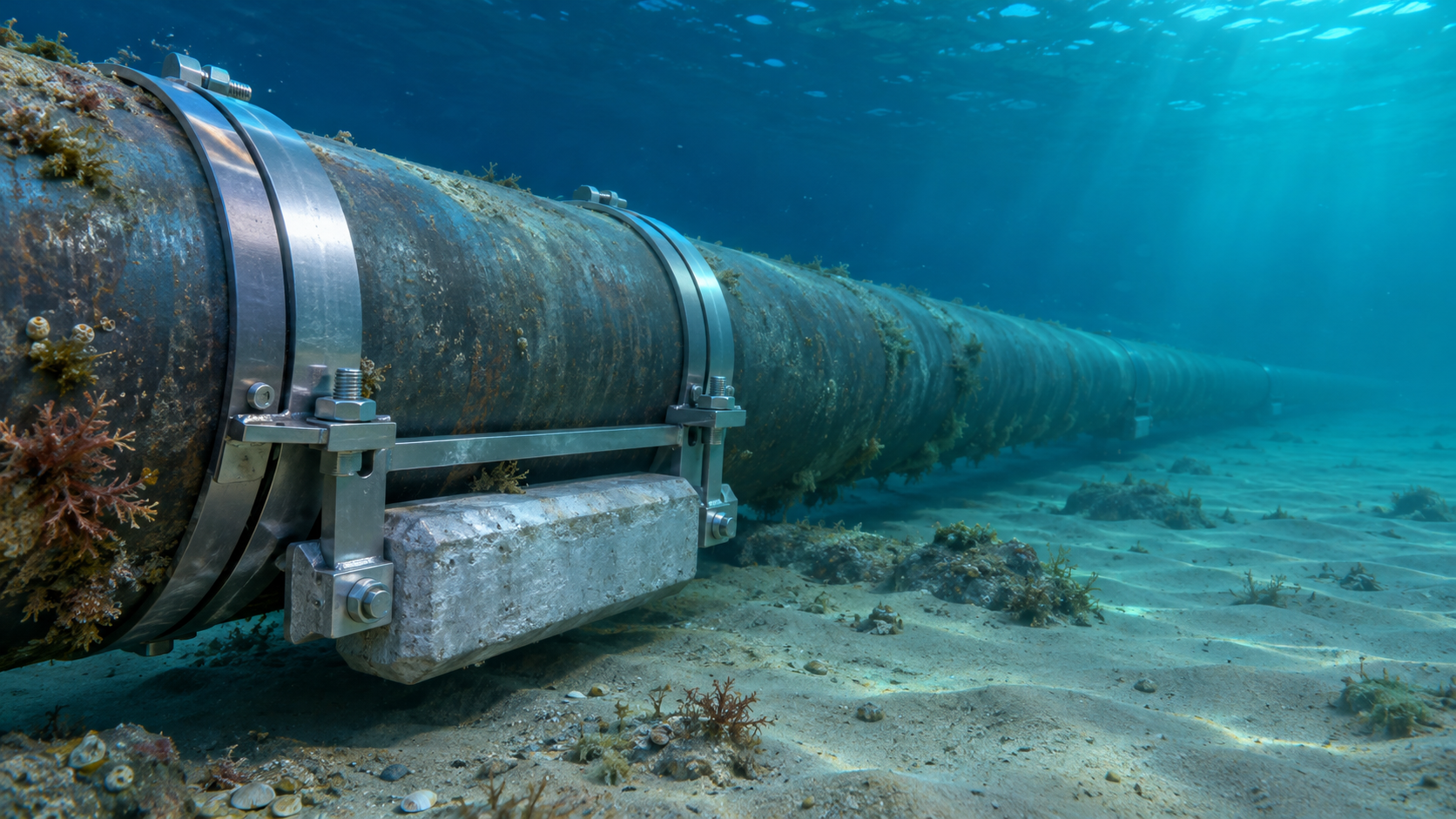
 Subsea Anode Retrofit Clamps: Sizing for Corrosion Protection LifeNov 06, 2026
- Global Project Radar: Tracking Pipeline Projects From Bid to AwardNov 06, 2026
- High-Frequency Induction Welded Pipe: Weld Quality and Heat InputNov 06, 2026
- Double Submerged Arc Welded Pipe: What to Check Before OrderingNov 06, 2026


Weekly Insights
Stay ahead with our curated technology reports delivered every Monday.
Questions about pipe blasting or corrosion protection? Leave a message for technical insights from GPIC.
We respect your privacy. Your information is strictly confidential.
Recommended News