Global Pipeline Knowledge
Unstable Pipe-to-Soil Readings: Troubleshooting Field Test Errors
A pipe-to-soil reading that will not settle can leave a field crew with an uncomfortable question: is the cathodic protection system changing, or is the measurement unreliable? A drifting display may result from poor reference electrode contact, a damaged lead, electrical interference, or a genuine change in operating conditions. Before treating the number as evidence of adequate or inadequate protection, operators need to establish what was measured and whether the setup can reproduce it.
This guide helps crews troubleshoot unstable readings, check Cathodic Protection Potential Testers, and record the conditions that give a voltage its meaning. It focuses on buried pipelines; subsea measurements require suitable equipment, procedures, and environmental interpretation.
Start by describing the instability
Not all fluctuating readings point to the same problem. Watch the display long enough to describe its behavior rather than recording whichever value appears at the moment.
- Slow drift: The reading moves gradually in one direction. Check electrode contact, electrolyte condition, changing soil moisture, and operating conditions.
- Sudden jumps: The value changes abruptly. Loose connections, movement of a lead, nearby switching equipment, or a cycling protection source may be involved.
- Repeating high and low values: A regular pattern can be consistent with an interrupted cathodic protection current, but the timing and source must be verified.
- Erratic or noisy display: Poor contact, damaged cables, electrical pickup, or an instrument problem are possible causes. Do not assume that every noisy reading is caused by interference.
Note the range, approximate timing, and whether the movement continues when the equipment is held still. A short observation can prevent a crew from spending time adjusting a rectifier when the real problem is a test lead that moves in its terminal.
Make the measurement setup repeatable
A pipe-to-soil potential is measured between an electrical connection to the pipeline and a reference electrode in contact with the surrounding electrolyte. The reported result depends on the electrode type, meter connections, electrode location, current flow, and measurement method. Check these basics before comparing the reading with a previous survey.
Check the pipe connection
Confirm that the test lead is connected to the intended pipeline terminal, not an adjacent casing, bond, coupon, or unrelated structure. Compare the test station identification and wiring with current records. Where procedures permit, inspect the terminal for corrosion, loose hardware, damaged insulation, or a conductor that is secure only when held at a particular angle.
With the instrument connected, gently move the accessible lead and clip. If the display changes in step with that movement, stop and correct the connection before proceeding. Do not bridge terminals, disconnect bonds, or disturb other equipment without authorization and an approved procedure.
Give the reference electrode reliable soil contact
A dry, dirty, damaged, or poorly maintained reference electrode can make a good pipeline connection look unreliable. For an electrode intended for soil use, inspect the porous contact surface and check its condition and electrolyte in accordance with the manufacturer’s instructions and the operator’s procedure. Use the reference electrode specified for the survey; do not assume different electrode types produce interchangeable readings.
Place the electrode at the prescribed location and make consistent contact with the soil. Remove loose debris if necessary. If the surface is exceptionally dry, follow the approved procedure for improving contact; uncontrolled wetting can change local conditions and make the result difficult to compare with other readings. Record any action taken.
Lift and replace the electrode at the same point, then repeat the measurement. If the reading changes each time, investigate contact and electrode condition before moving on. A comparison with a verified reference electrode, performed according to the applicable procedure, can help identify a suspect electrode. Both electrodes need suitable contact for that comparison to be meaningful.
Keep placement and polarity consistent
Moving the electrode can produce a different reading even when nothing is wrong with the meter. Potential gradients in the soil, nearby structures, coating condition, and current paths can all influence the result. Take the electrode position specified by the survey procedure, often at or near the pipe location, and document deviations when the pipe cannot be accessed directly.
Check the test lead polarity and the instrument’s sign convention. A reversed connection can reverse the displayed sign; it does not turn the reading into a different protection state. Record the value with its sign, units, reference electrode type, and lead arrangement.
Check Cathodic Protection Potential Testers without changing the system
A tester should be checked systematically rather than blamed simply because the display moves. Use an instrument suitable for the measurement method, with input characteristics appropriate for pipe-to-soil testing and the expected circuit resistance. The operator’s procedure and instrument manufacturer should define the required checks.
- Inspect the instrument and leads. Look for damaged sockets, cracked insulation, contaminated plugs, weak clips, and signs of moisture entering the equipment.
- Check the battery and settings. Confirm the correct measurement mode, range, polarity, and any filtering or recording settings. A low battery or unsuitable range can affect usability or measurement quality.
- Verify function against a suitable known source. Use the operator’s approved check method and confirm calibration status where required. A functional check in the field is not automatically a substitute for calibration.
- Compare components one at a time. If a second verified tester, lead, or electrode is available, substitute one component while keeping the remaining setup and measurement location unchanged.
- Repeat and record. A stable result after a substitution is useful evidence, but retain the original observation and identify what changed.
For example, if replacing the electrode makes the reading repeatable while the same meter, leads, and location are retained, the original electrode or its contact deserves attention. If two verified meters show the same cycling pattern, the pattern may reflect conditions in the circuit rather than a fault in both instruments.
When the reading is real: current, interference, and timing
A stable setup does not guarantee a stable pipeline potential. The protection system and surrounding electrical environment may genuinely change during a survey. Record the time carefully and ask the control room or responsible corrosion team whether relevant equipment was operating, switching, or under test.
Understand “on” and “instant-off” readings
An on potential is measured while cathodic protection current is flowing. It can include a voltage drop through the electrolyte, commonly called IR drop. An instant-off potential is taken immediately after the relevant protection current is interrupted, with the intention of reducing the contribution from that current-related voltage drop before significant depolarization occurs.
Obtaining a meaningful instant-off reading is not as simple as switching off one rectifier. Other current sources, bonds, or interconnected systems may continue to influence the measurement. Interruption timing, synchronization, instrument response, and the selected sampling window matter. Switching transients can also distort the value captured immediately after interruption.
Use the approved interruption plan and suitable recording equipment. Do not interrupt protection sources or alter bonds without authorization and coordination. If the required sources cannot be identified or controlled, flag that limitation rather than labeling an uncertain value as a valid instant-off potential.
Look for external influences
Stray direct current from nearby systems, changes in adjacent cathodic protection installations, and electrical activity associated with rail or industrial facilities can cause time-varying potentials. AC power infrastructure can introduce electrical effects and safety hazards. A fluctuating DC reading alone does not identify the source, and a standard potential measurement alone does not establish whether an AC hazard exists.
If the pattern persists with verified equipment, record its timing and range and refer it for a coordinated interference investigation. That may require measurements at multiple locations, synchronized data, operating information from neighboring systems, or additional testing. Follow site electrical safety requirements and stop work if unexpected voltage or an unsafe condition is suspected.
Use the pattern to choose the next check
If a reading cannot be made repeatable, report it as unstable or inconclusive under the operator’s procedure. Avoid averaging an unexplained range into a single apparently precise value. A time-stamped recording may be more useful than a spot reading when the variation itself is the evidence.
Compare results only when the methods match
A previous test station record can be valuable, but a difference from last year is not automatically deterioration. Check whether the earlier survey used the same electrode type, placement, polarity, current condition, and measurement method. Seasonal moisture, access changes, protection system operation, nearby construction, and survey timing may also affect comparability.
The applicable protection criterion must be identified by its standard or regulatory basis, edition, environment, and measurement method. A commonly cited numerical threshold should not be applied indiscriminately to an on reading, a different reference electrode, or a measurement with unresolved interference. Some criteria also require information beyond a single potential reading. Use the project’s approved assessment procedure and refer uncertain results to the responsible corrosion engineer.
Likewise, a satisfactory reading at one test station does not prove that every part of the pipeline is protected. It is one piece of evidence alongside survey coverage, coating condition, electrical continuity, isolation, interference assessments, and other integrity information.
Leave a record another crew can use
Good troubleshooting notes make the next visit more productive, especially when the fault is intermittent. Record the pipeline and test station identification, date and time, instrument and electrode identification, electrode type and location, reading sign and units, and whether the value was on, instant-off, or obtained by another defined method.
Include the range and pattern of any fluctuation, soil and access conditions, known equipment operation, substitutions made, and the result of each check. Note deviations from the procedure and unresolved limitations. If the reading suggests a potential protection concern, escalate it through the operator’s integrity process rather than waiting for the next routine survey.
The goal is not to force an unstable display into a neat number. It is to separate measurement error from changing field conditions, preserve the evidence, and give the people responsible for the pipeline a defensible basis for the next decision.
Related Industries
Trending in Tech
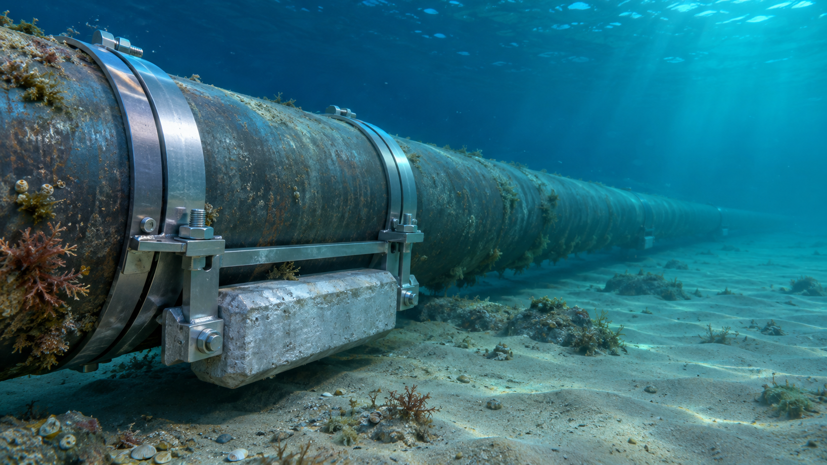
 Subsea Anode Retrofit Clamps: Sizing for Corrosion Protection LifeNov 06, 2026
- Global Project Radar: Tracking Pipeline Projects From Bid to AwardNov 06, 2026
- High-Frequency Induction Welded Pipe: Weld Quality and Heat InputNov 06, 2026
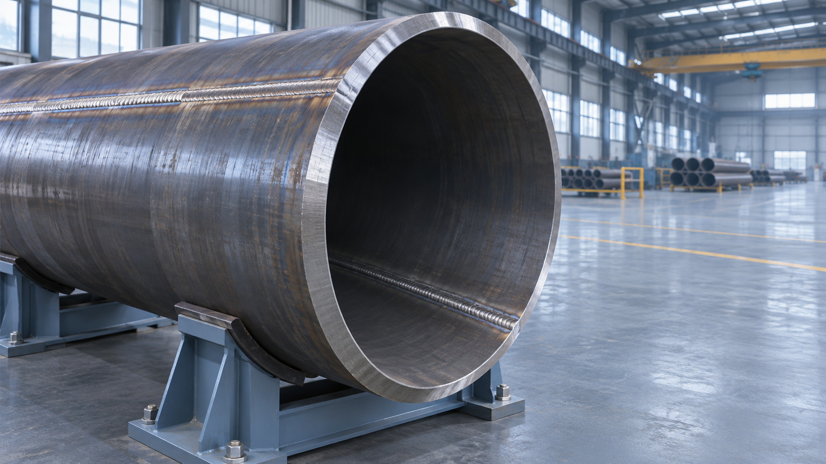
- Double Submerged Arc Welded Pipe: What to Check Before OrderingNov 06, 2026


Weekly Insights
Stay ahead with our curated technology reports delivered every Monday.
Questions about pipe blasting or corrosion protection? Leave a message for technical insights from GPIC.
We respect your privacy. Your information is strictly confidential.
Recommended News