Global Pipeline Knowledge
Cathodic Protection Potential Testers: How Pipe-to-Soil Readings Work
Cathodic protection potential testers measure the voltage between a pipeline and a reference electrode in contact with the surrounding soil. The resulting pipe-to-soil reading provides evidence about the pipe’s electrochemical condition at the time and place of measurement. Its meaning depends on the reference electrode, where it is placed, whether protective current is flowing, and which assessment criterion applies.
A more negative number is not automatically proof of better protection. Two readings at the same test station can differ because one includes voltage losses in the soil while the other was captured after a current source was interrupted. Understanding that distinction is essential before comparing values or deciding whether further investigation is needed.
What a pipe-to-soil reading measures
A buried steel pipeline in soil forms part of an electrochemical system. Cathodic protection supplies current to the pipe to shift its potential in a direction that reduces the tendency for steel to corrode. A potential tester measures the voltage between an accessible metallic connection to the pipeline and a reference electrode placed in contact with the soil.
The reference electrode provides a stable comparison potential; it does not measure the steel’s potential in isolation. The displayed value is the difference between the pipe connection and the electrode under the existing electrical conditions. Reference electrode type matters because different electrode systems have different reference potentials. A numerical value quoted against a copper/copper sulfate electrode should not be compared directly with a value quoted against a different reference electrode without the appropriate conversion and context.
For buried pipelines, a copper/copper sulfate reference electrode is commonly used. The electrode requires a sound porous contact surface, suitable electrolyte condition, and electrical contact with the soil. Dry ground, contamination, a damaged tip, or poor contact can produce unstable or misleading readings. Electrode condition is therefore part of the measurement, not a separate housekeeping detail.
From test station to voltage display
A typical measurement uses a high-input-impedance voltmeter or a dedicated potential tester, test leads, a reference electrode, and an electrically continuous connection to the pipeline. The connection is often available at a test station, although other verified metallic connections are used where appropriate.
With the instrument configured to display pipe potential relative to the reference electrode, the pipe lead is connected to the pipe terminal and the reference lead to the electrode. The electrode is placed on soil above or close to the pipe, with its tip making firm contact. The displayed polarity should be checked against the instrument’s connection convention: reversing leads reverses the sign without changing the physical condition of the pipeline.
The exact electrode position matters. Voltage gradients exist in soil when current flows, so moving the electrode even within the same test area can change the reading. A location directly above the pipe is commonly used for repeatable surveys, but it is not necessarily the position of the exposed steel at a coating defect. Depth of cover, nearby anodes, other buried structures, and surface conditions all influence the path between the defect and the electrode.
Good repeatability starts with recording the location and setup, including the pipe connection, electrode type and placement, meter polarity, date, and cathodic protection operating state. A value without these details is difficult to compare with a later reading or use in an engineering assessment.
On potential and the effect of current in soil
An on potential is measured while the relevant cathodic protection current sources are operating. It is straightforward to collect and useful for tracking changes at established monitoring points. A shift from previous readings can indicate a change in rectifier output, continuity, interference, soil conditions, or the measurement setup.
The on reading includes more than the polarized potential at the steel surface. Current flowing through soil creates a voltage difference across the soil’s electrical resistance, often called an IR drop. That component is included in the measured voltage between the pipe connection and the surface electrode. Its size and direction depend on the current paths, electrode location, and surrounding resistivity.
For example, an on reading that appears sufficiently negative under a particular criterion may include a significant soil-voltage component. The pipe surface at a coating defect could be less negative than the display suggests. Conversely, a change in on potential does not by itself establish that corrosion protection has improved or deteriorated; a change in current distribution can alter the measurement even when the underlying condition is harder to judge.
On readings still have value. They reveal the voltage present with the system operating and can help locate unusual gradients or changes over time. Their limitation is that a single on value does not separately identify the polarized steel potential and the voltage associated with current flow through the environment.
Instant-off readings and their limits
An instant-off potential is captured immediately after relevant cathodic protection current sources are switched off. Interrupting current reduces the associated soil IR drop, while the pipe surface initially retains much of its polarization. The result is intended to provide a closer indication of polarized potential than an on reading alone.
Timing is central. If the reading is taken too early, switching transients or residual current effects can distort it. If taken too late, the pipe may already be depolarizing, so the reading no longer represents the intended instant-off condition. Dedicated instruments and synchronized interrupters can capture a repeatable point in the interruption cycle, but the timing must match the survey procedure and the electrical behavior of the system.
All significant sources affecting the measurement need consideration. A pipeline may receive current from several rectifiers, neighboring systems, or galvanic anodes. If only one source is interrupted, current from the others can continue to produce IR drop. Sources that cannot be interrupted, including some galvanic anode arrangements, require a different assessment approach. Switching a rectifier off therefore does not automatically make a reading IR-free.
Interruption can also affect connected assets and must be planned around electrical continuity and interference. The interpretation of an instant-off value should identify which sources were interrupted, whether their cycles were synchronized, and whether other current sources remained active.
Reading a potential against a protection criterion
A protection criterion is a rule for evaluating evidence under defined conditions. It is not simply a voltage printed on a meter. Criteria can specify a reference electrode, measurement technique, treatment of voltage drops, environment, and limitations. The governing standard or project procedure, including its applicable edition, determines which criterion and supporting evidence are relevant.
Common approaches include assessing a suitably corrected polarized potential or assessing a specified amount of polarization. These are different tests. A polarization shift requires a valid comparison between defined potential states; it cannot be determined from one isolated reading. Establishing a suitable baseline and allowing for the way the pipeline responds to interruption are part of that assessment.
As an illustration of interpretation rather than an acceptance limit, suppose an on reading is substantially more negative than the corresponding instant-off reading. The separation suggests that current-related voltage effects or interruption behavior deserve attention. It does not quantify the condition of every coating defect along the pipeline, and it does not establish acceptance without the applicable criterion and measurement details.
Very negative potentials also deserve context. Excessive cathodic polarization can create concerns for certain coatings or susceptible materials, but a raw on reading alone cannot establish that the steel surface has reached a harmful polarized condition. Electrode placement, current distribution, measurement method, and material-specific limits all matter.
When similar numbers tell different stories
Two test stations can show the same voltage while representing different conditions. At one station, protective current may be well distributed and the reading relatively stable. At another, a nearby current source may create a large soil voltage gradient, masking a less favorable potential at the steel. A single display value does not distinguish those situations.
Electrical continuity is equally important. A test lead connected to a casing, bond wire, or isolated section does not necessarily represent the intended carrier pipe. A loose terminal or damaged lead can cause unstable readings or produce a measurement of the wrong structure. The connection should be identified and verified before interpreting an unexpected value as a change in pipeline condition.
Soil and surface conditions also affect the survey. Wetting the ground around an electrode can improve electrical contact in dry soil, but the method and placement should remain consistent with the procedure. Standing water, contaminated electrode solution, and contact with unsuitable material can introduce their own problems. A stable display is useful, but stability alone does not prove that the electrode is functioning correctly.
Stray direct current presents a different challenge. If potentials fluctuate with time, a single spot reading can miss the range of exposure. Time-based recording, paired with investigation of the source and current paths, gives more useful evidence than treating one momentary value as representative. Alternating current interference is a separate concern; a satisfactory direct-current potential reading alone does not establish that alternating-current corrosion or electrical safety risks have been addressed.
Spot readings, surveys, and coverage
A test-station reading describes the electrical relationship at a particular connection, electrode position, and time. Current distribution along a pipeline is not uniform, particularly where coatings vary, branches or bonds alter continuity, or nearby structures influence current flow. A satisfactory point reading therefore cannot establish that every section between stations meets the same criterion.
Close-interval potential surveys collect readings at successive locations along a route and can reveal changes that widely spaced test stations miss. Their interpretation still depends on electrode placement, interruption quality, access to the pipeline route, and the presence of interference. They are measurements from the ground surface, not a direct view of every exposed area of steel.
Coupons or probes installed near a pipeline can provide supplementary evidence under a defined arrangement. A coupon is an exposed metal sample connected to the structure; disconnecting it for measurement can reduce certain voltage-drop effects at that sample. Its potential represents the coupon and its local environment, however, and is not automatically identical to the potential at every coating defect on the pipe. Coupon size, placement, connection, and exposure history affect the result.
Where readings are unexpected, the most useful next evidence often comes from revisiting the measurement conditions: confirm the structure connection, reference electrode, placement, instrument settings, and current-source state. A repeatable measurement with those details recorded gives subsequent survey or direct examination work a defensible starting point.
Related Industries
Trending in Tech
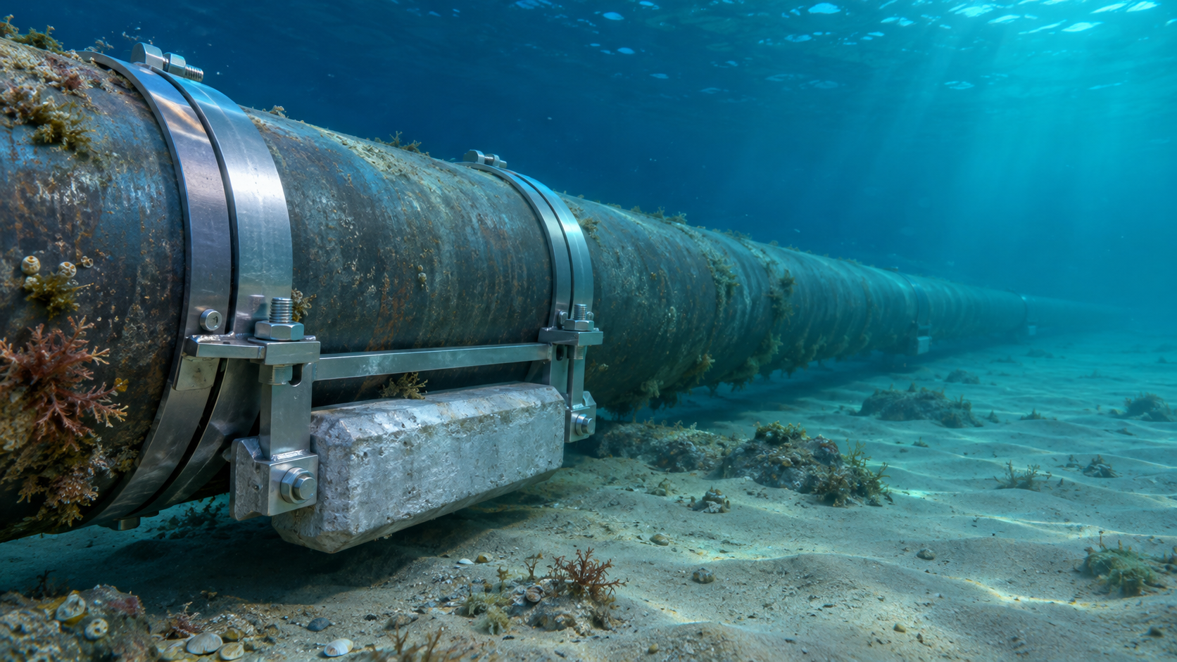
 Subsea Anode Retrofit Clamps: Sizing for Corrosion Protection LifeNov 06, 2026
- Global Project Radar: Tracking Pipeline Projects From Bid to AwardNov 06, 2026
- High-Frequency Induction Welded Pipe: Weld Quality and Heat InputNov 06, 2026
- Double Submerged Arc Welded Pipe: What to Check Before OrderingNov 06, 2026

Weekly Insights
Stay ahead with our curated technology reports delivered every Monday.
Questions about pipe blasting or corrosion protection? Leave a message for technical insights from GPIC.
We respect your privacy. Your information is strictly confidential.
Recommended News