Global Pipeline Knowledge
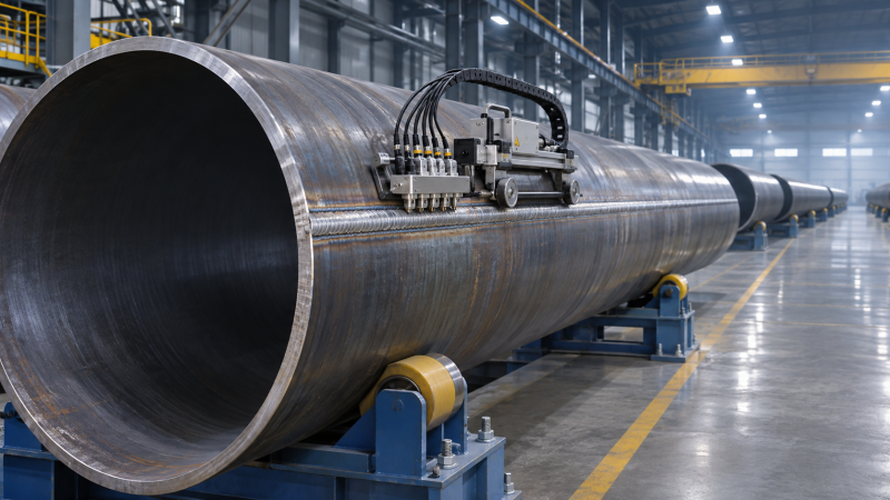
3LPE Field Joint Coatings: Surface Preparation and Testing
Three-Layer Polyethylene Field Joint Coatings protect exposed weld areas where a pipeline’s factory-applied coating has been interrupted. Their performance depends on more than coating selection: surface cleanliness, anchor profile, application conditions, and verification testing all influence the quality of the finished joint. For quality control and safety personnel, understanding these factors is essential to identifying defects, documenting compliance, and reducing corrosion risks.
The difficult part is often the transition, not the middle of the weld. A field joint must bond to prepared steel and seal against the existing line coating, despite changes in geometry, working conditions, and application crew. A joint can look acceptable after installation yet contain contamination at the steel interface, inadequate overlap, or a poorly consolidated sleeve. Once the pipe is buried or laid offshore, finding and correcting that weakness becomes much harder.
Start with the coating system, not a generic checklist
Factory-applied 3LPE generally comprises an epoxy layer, a polymeric adhesive, and a polyethylene outer layer. The field-joint system must provide a compatible connection across the cutback, but it is not necessarily applied in the same way as the factory coating. A qualified system may use an epoxy primer with a heat-shrink sleeve and adhesive; other approved configurations are also used. The manufacturer’s instructions and project qualification documents determine the actual sequence.
Before work starts, establish which document controls each requirement. ISO 21809-1 addresses factory-applied three-layer polyethylene and polypropylene coatings for buried or submerged pipeline transportation systems; ISO 21809-3 addresses field-joint coatings. Their applicability depends on the contract, specified edition, coating type, and project scope. A factory coating requirement should not automatically be treated as the field-joint acceptance criterion.
The inspection and test plan should identify the approved procedure, qualification evidence, hold points, inspection frequency, acceptance limits, and repair route. Where the project specification and manufacturer’s instructions differ, resolve the conflict before production rather than allowing crews to choose whichever limit is easier to meet.
Surface preparation begins before blasting
Coating work should not conceal an unresolved welding issue. Confirm that required weld inspection and any repairs have been completed and released. Weld spatter, sharp edges, slag, and protrusions can prevent intimate coating contact or create local stress points. Their treatment should follow the approved welding and coating procedures, without unauthorized grinding that could affect the weld or pipe wall.
Remove oil and grease before abrasive blasting. Blasting a contaminated surface can spread the residue rather than reliably eliminate it. Check the cutback area and surrounding line coating for dirt, moisture, damage, and handling contamination as well: the sleeve overlap needs a prepared substrate, not merely clean exposed steel.
Abrasive selection and equipment condition matter. Contaminated abrasive or oil and water carried by compressed air can undo otherwise good preparation. Verify abrasive cleanliness and compressed-air quality using the project’s specified checks, and protect prepared surfaces from dust generated by adjacent operations.
Cleanliness and profile are different requirements
Visual cleanliness assesses the condition of the prepared steel; surface profile describes the roughness available for coating adhesion. Passing one does not establish the other. ISO 8501-1 provides visual grades for surface cleanliness, while the ISO 8503 series covers characteristics and assessment of blast-cleaned steel profiles. Use the editions and methods identified in the project documents.
A surface that appears uniformly bright may still have an unsuitable profile. Too little roughness can compromise bonding; an excessive or uneven profile can make it difficult to achieve the intended coverage over peaks. Measure at the required locations with the specified instrument or comparator, and record the result against the approved range. Do not borrow a profile range from another sleeve system or a factory-coating procedure.
Soluble salts require separate attention where specified. They may remain on a surface that looks clean and can contribute to coating deterioration in service. The ISO 8502 series includes methods relevant to assessing surface contamination, including soluble salts. The test method, sampling location, frequency, and acceptance limit must be agreed for the project; visual inspection alone cannot verify salt cleanliness.
Control the interval between preparation and application
Prepared steel is vulnerable to condensation, flash rust, and contamination. Measure steel temperature and ambient conditions as required, calculate or determine dew point using the approved method, and confirm the specified separation before coating. Repeat the checks when conditions change or when work has been interrupted. A reading taken at the start of a shift does not establish conditions at every joint later that day.
The time allowed between blasting and coating is not a substitute for examining the surface. If windblown dust, rain, condensation, or visible oxidation appears, stop and assess whether cleaning or reblasting is required under the approved procedure. In a humid trench or an offshore firing line, waiting for the next planned inspection may leave too little time to correct the condition without disrupting production.
The existing polyethylene coating also needs the prescribed preparation at the overlap. Depending on the qualified system, this may include cleaning, abrading, and preparing the coating edge. Excessive abrasion or uncontrolled heating can damage the parent coating, while insufficient preparation can leave a weak transition. Inspect the full circumference, including the underside, where access and visibility are often poorest.
Application conditions leave evidence on the joint
Preheat must be measured on the pipe, not inferred from flame time. Pipe wall thickness, wind, and access can produce uneven temperatures around the circumference. Check the locations and temperature range required by the procedure, using suitable, verified instruments. Confirm that primer mixing, induction time where applicable, pot life, application thickness, and the interval before sleeve installation remain within the qualified system’s limits.
For a heat-shrink sleeve, the crew must control positioning, overlap, heating, and consolidation. Wrinkles, trapped air, exposed adhesive, scorching, or an uneven closure can indicate an application problem, although visual appearance alone does not prove bond quality. Adhesive flow at the edges may be one sign used in the manufacturer’s procedure; it is not a universal replacement for specified inspection or testing.
Safety controls need to match the work location. Open-flame heating near flammable materials, welding activities, enclosed excavations, or adjacent coatings requires a task-specific assessment and the applicable permit controls. Manage ventilation, fire watch, hot surfaces, lifting arrangements, and access under the pipe. Abrasive blasting also requires controls for airborne dust, noise, and exposure to the abrasive and removed material. A coating schedule should not force personnel to work in an unsafe trench or bypass a hold point.
Testing: what each check can and cannot establish
Visual inspection is the first screening step after application and cooling to the condition specified for inspection. Check coverage, sleeve position, overlap, closure, burns, wrinkles, lifted edges, and obvious mechanical damage. Pay particular attention to the weld crown and the transition onto the factory coating. Record the location of defects so repairs can be verified, rather than describing the joint simply as “unsatisfactory.”
Holiday detection checks electrical discontinuities in the coating system under the selected test conditions. ISO 29601 addresses holiday detection for protective coatings; the project must specify the applicable method, equipment, test voltage, grounding, electrode arrangement, and acceptance criteria. Voltage selection depends on the coating system and thickness and must follow the governing procedure. An inappropriate setting can miss defects or damage the coating. A holiday-free result does not demonstrate adequate adhesion or prove the absence of contamination beneath an apparently continuous coating.
Thickness measurements can identify insufficient or inconsistent coverage where the method is suitable for the system. For a multilayer or sleeve construction, clarify what the instrument is measuring and whether the acceptance limit applies to an individual layer or the completed assembly. Weld geometry and the underlying line-coating transition can affect readings. Verify the instrument and take measurements at the locations and frequency specified in the inspection plan.
Adhesion or peel testing provides different evidence. It may be destructive and may assess the steel interface, the overlap onto the line coating, or another part of the system, depending on the specified method. Test temperature, direction, rate, sample preparation, and failure mode all affect interpretation. A numerical peel result without those conditions is difficult to compare with a qualification result or another project. Any test site that damages the coating must be repaired and re-inspected.
Qualification testing and production inspection should not be confused. Qualification may include performance tests under defined laboratory conditions, such as resistance to cathodic disbondment or other properties required by the specification. Those results support the selected system and procedure; they do not establish that every field joint was prepared and installed correctly. Conversely, routine field checks do not reproduce the full qualification programme.
Repair, release, and the installation that follows
A nonconforming joint needs more than a quick patch over the visible mark. Determine the extent and likely cause: a local handling defect calls for a different response from widespread poor adhesion or contamination. Use a repair material and method compatible with the field-joint and parent coating systems. Where the approved procedure requires removal and recoating, do not substitute a smaller repair simply to recover schedule. Reinspect and retest the repaired area as specified.
Release documentation should link the joint number to surface-preparation results, environmental readings, materials and batch details, application records, test results, repairs, and inspector acceptance. The level of detail should follow the project plan, but it must be sufficient to investigate a recurring defect across a crew, material batch, shift, or section of line.
A passed joint can still be damaged during lowering-in, padding, backfilling, or offshore installation. The release point should therefore be clear: identify who checks for subsequent damage and when further holiday inspection or repair is required. Coating condition also affects cathodic protection demand, but cathodic protection should not be used as a reason to accept known coating defects.
Before approving the next production shift, review the actual failures and interruptions, not just the percentage of joints released. Repeated repairs at the same overlap, for example, warrant a review of surface preparation, heating, access, and crew technique. That conversation is most useful while the pipe is still accessible and the application records can be checked against the work itself.
Related Industries
Trending in Tech
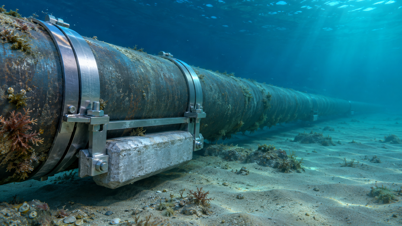
 Subsea Anode Retrofit Clamps: Sizing for Corrosion Protection LifeNov 06, 2026
- Global Project Radar: Tracking Pipeline Projects From Bid to AwardNov 06, 2026
- High-Frequency Induction Welded Pipe: Weld Quality and Heat InputNov 06, 2026
- Double Submerged Arc Welded Pipe: What to Check Before OrderingNov 06, 2026


Weekly Insights
Stay ahead with our curated technology reports delivered every Monday.
Questions about pipe blasting or corrosion protection? Leave a message for technical insights from GPIC.
We respect your privacy. Your information is strictly confidential.
Recommended News