Global Pipeline Knowledge
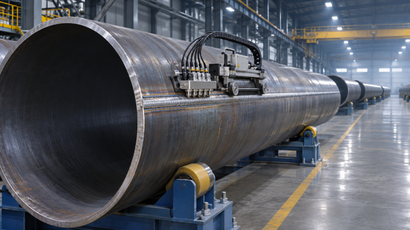
Uneven FBE Coating Thickness: What to Check on the Coating Line
Uneven fusion-bonded epoxy (FBE) thickness can appear as a narrow thin band, a difference between the two ends of a pipe, or a gradual change across an entire production run. Each pattern points to a different set of checks. Adding more powder may conceal a low reading temporarily, but it can also create excessive buildup elsewhere without correcting the cause.
Start by confirming that the readings are reliable and mapping where the variation occurs. Then compare that pattern with pipe temperature, powder delivery, spray settings, rotation, and line speed. Keep affected pipe identifiable while the line is investigated: an acceptable average thickness does not establish that every required location meets the project specification.
First, establish what “uneven” means
A thickness map is more useful than a single minimum and maximum. Record readings around the circumference and along the pipe using the locations and sampling frequency required by the project’s inspection procedure. Include the pipe identification, orientation, measurement positions, and whether the readings were taken before or after any subsequent coating operation.
The shape of the variation helps narrow the investigation:
- A thin area in the same circumferential position: Check spray-gun coverage, gun alignment, local shielding, rotation, and any position-dependent heating or measurement issue.
- A repeating spiral or band: Compare the pattern with pipe rotation, travel speed, gun positioning, and fluctuations in powder output.
- One end consistently different: Examine heating and application conditions near the pipe ends, including spray start and stop timing and the specified cutback area.
- Thickness changing from pipe to pipe: Look for changes in temperature, powder supply, conveyor behavior, and production settings over time.
- Isolated low or high readings: Verify the measurement location and surface condition before treating them as evidence of a line-wide problem.
These patterns are diagnostic clues, not proof of a single cause. A rotating pipe can carry a short-lived powder-delivery fluctuation into a spiral pattern, for example, while an apparent circumferential pattern may be affected by how the pipe was indexed during measurement. Preserve the original readings and mark the pipe orientation so that subsequent checks can be compared consistently.
Verify the measurement before changing settings
Use the project-approved dry-film thickness method and a suitable, calibrated gauge. Check the instrument against its reference standards and follow the gauge and inspection procedures for verification, adjustment, and measurement on the relevant substrate and geometry. A gauge that passes a basic check can still produce misleading results if it is used incorrectly on a curved surface or if the probe does not sit properly.
Inspect the measurement area for dirt, loose material, damage, unusual surface profile, or other conditions that could affect probe contact. Check whether the procedure calls for any treatment of substrate roughness in interpreting the result. Do not subtract a guessed profile value or change the acceptance basis to make a reading fit.
Repeat questionable readings at the original location and nearby positions. Where practical, have a second qualified inspector check the same area with another verified gauge. Record both sets of results rather than replacing the first set. If the pipe or coating is still hot, follow the instrument manufacturer’s temperature limits and the approved inspection procedure; heat can affect the gauge, the probe, or the consistency of contact.
Also distinguish the specified coating area from the intentional uncoated cutback at each end. A transition close to a cutback may need a specific assessment under the project requirements. It should not be judged as ordinary full-body coverage without checking those requirements.
Check pipe temperature at the point of application
FBE powder must encounter a suitably heated surface to melt and form the intended coating. A pipe can leave the heating equipment with an acceptable displayed temperature yet arrive at the spray area with a different temperature, particularly if there is a delay or an uneven temperature distribution.
Compare the measured pipe temperature with the approved application window for the specific powder and coating system. Check at representative locations around the circumference and along the length, including areas associated with low or high thickness. Use a verified temperature-measurement method suitable for the surface and production conditions.
If one area is consistently cooler, investigate heater distribution, pipe rotation through the heating zone, line speed, and the time between heating and powder application. Check sensors and control readings as well as the pipe itself. A control display represents the point and method being monitored; it does not automatically establish that the whole coating surface is uniform.
A temperature problem can affect more than film thickness. Melting, flow, cure, and adhesion may also be affected, so restoring the thickness reading alone is not sufficient to release suspect pipe. Follow the approved inspection and disposition process for the affected coating.
Trace powder delivery from the feed system to the guns
Once the measurement and temperature are credible, check whether the spray equipment is delivering a stable, repeatable powder pattern. Review the powder hopper level, fluidization, feed lines, filters, pumps, hoses, and guns using the equipment supplier’s procedures. Restrictions, leaks, inconsistent air supply, worn parts, or powder buildup can change output or disrupt the spray pattern.
Look for differences between guns serving the thin and thick areas. A partially obstructed nozzle, a changed gun angle, or buildup on an electrode can alter where powder is deposited. Gun-to-pipe distance and positioning also matter, especially near pipe ends or where the coverage patterns of adjacent guns overlap.
Check the electrostatic settings and the pipe’s electrical grounding as part of the approved line checks. Poor grounding or unstable settings can affect powder attraction and distribution. Operators should use the equipment’s prescribed isolation and safety procedures before inspecting, cleaning, or adjusting spray equipment.
Powder condition deserves the same attention as hardware. Confirm that the material is the approved product and batch, is within its permitted storage and use conditions, and has been handled in accordance with the manufacturer’s instructions. Where recovered powder is used, check that its proportion and condition meet the coating manufacturer’s and project’s requirements. Contamination or inconsistent feed characteristics can complicate both application and coating performance.
Do not compensate for a blocked or poorly positioned gun simply by increasing total powder feed. That may raise thickness in areas already receiving adequate coverage while leaving a local defect unresolved. Restore stable delivery first, then adjust output against measured results.
Match rotation and travel to the spray pattern
On Pipe Coating Lines, the deposited film depends on how long each surface area remains exposed to the powder cloud. Changes in pipe rotation, forward travel, gun output, or their relationship can therefore produce variations even when each individual setting appears plausible.
Compare actual operating conditions with the approved production settings and the values recorded when acceptable pipe was produced. Check for slipping drive rollers, inconsistent pipe contact, speed fluctuations, or control changes during acceleration and deceleration. A displayed setpoint should be checked against actual movement when the pattern suggests that rotation or travel is unstable.
If the thin area follows a repeatable helical path, examine whether changes in rotation or travel coincide with the spacing and direction of the pattern. A regular spiral can indicate a coverage or overlap problem; an irregular pattern may call for closer attention to intermittent powder feed, unstable movement, or fluctuating application conditions. Neither observation identifies the cause on its own.
End effects need separate attention. Pipe entry and exit can change exposure time, while spray start and stop controls determine how close the coating reaches the specified cutback. Check the timing, pipe detection, gun arrangement, and movement through the booth before adjusting the cutback or accepting an irregular transition.
Change one condition, then prove the result
Multiple simultaneous adjustments make it difficult to tell which condition caused the variation. After addressing an obvious equipment fault or safety issue, make a controlled change under the approved operating procedure, document it, and inspect the resulting pipe. Compare the new thickness map with the original pattern, not just the overall average.
A useful production record connects the measured result to the conditions that produced it:
- Pipe identification, dimensions, orientation, and measurement locations.
- Powder product and batch, including the relevant feed arrangement.
- Pipe temperature readings and where and when they were taken.
- Line speed, rotation, gun configuration, and relevant application settings.
- Observed fault, corrective action, and inspection results after the change.
If the pattern persists after a plausible adjustment, return to the evidence. For example, increasing powder output without improving a localized thin band should prompt another look at gun alignment, obstruction, grounding, pipe movement, or the measurement itself. Escalate to the coating supervisor, quality personnel, or equipment and powder specialists when the line cannot be brought back within its approved operating conditions.
Decide what happens to the affected pipe
Identify the last pipe known to have met the applicable requirements and define the potentially affected production since that point. Hold or segregate suspect pipe in accordance with the project quality procedure until inspection establishes its status. The extent of the hold depends on the evidence available, including when the variation began and whether the relevant process records are trustworthy.
Acceptance must follow the contract and the applicable coating specification, including its edition, measurement method, required locations, and limits. Do not assume that an average reading, a single passing spot, or a later successful pipe clears the earlier production. Equally, an unusual thickness pattern is not automatically a rejection if all applicable requirements are met and the inspection procedure supports that conclusion.
Where coating is outside the specified limits, use the approved disposition route. Repair, stripping and recoating, additional examination, or rejection may be appropriate depending on the defect, coating system, and project rules. Excessive thickness also warrants assessment against the specified upper limit and any related performance requirements; applying more powder is not a universal remedy.
Before returning to normal production, verify that the corrective action has produced consistent coverage at the required locations and complete any other inspections or tests triggered by the event. The aim is to establish both a stable line and a traceable disposition for the pipe produced while the condition was present.
Related Industries
Trending in Tech
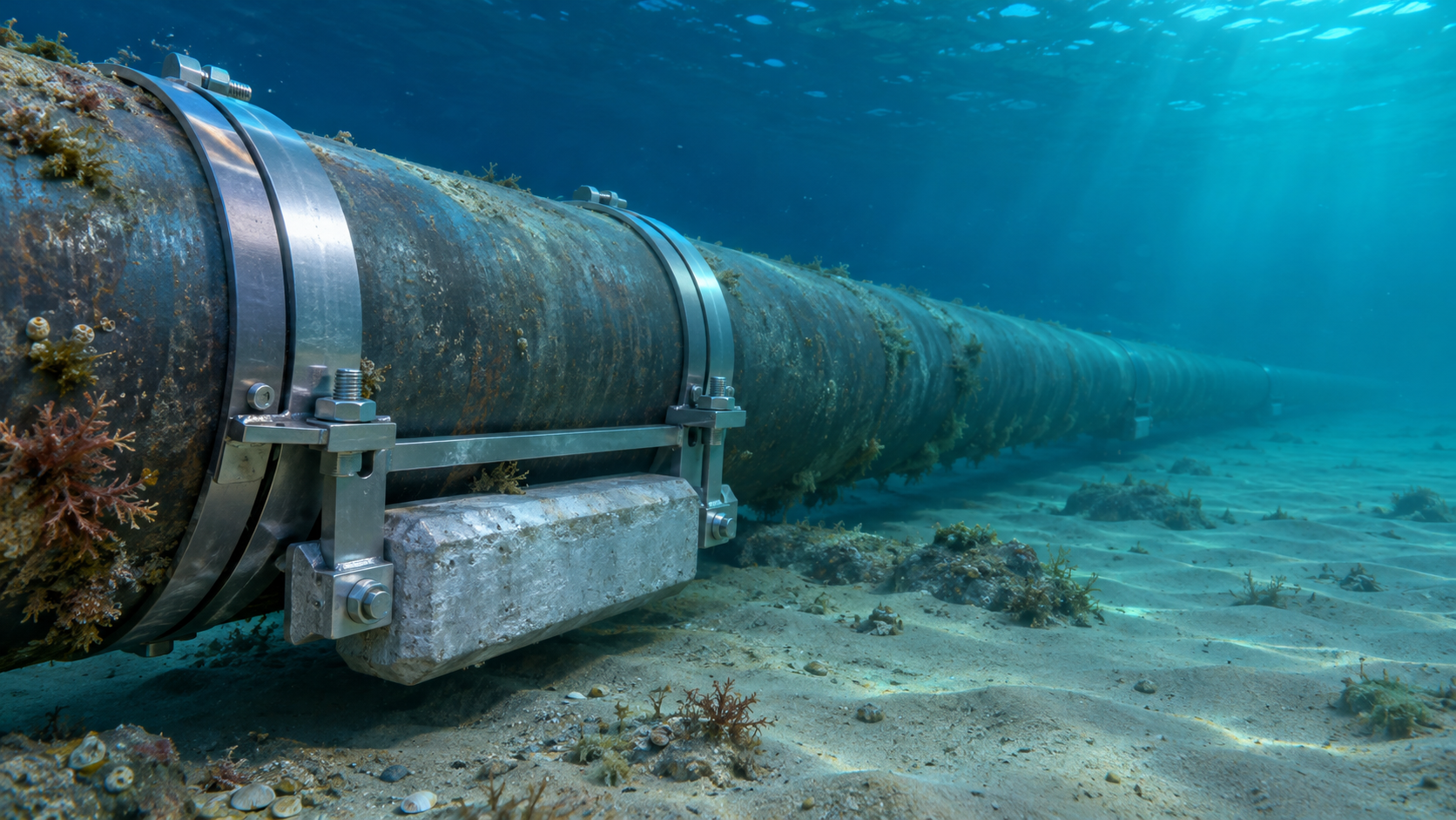
 Subsea Anode Retrofit Clamps: Sizing for Corrosion Protection LifeNov 06, 2026
- Global Project Radar: Tracking Pipeline Projects From Bid to AwardNov 06, 2026
- High-Frequency Induction Welded Pipe: Weld Quality and Heat InputNov 06, 2026
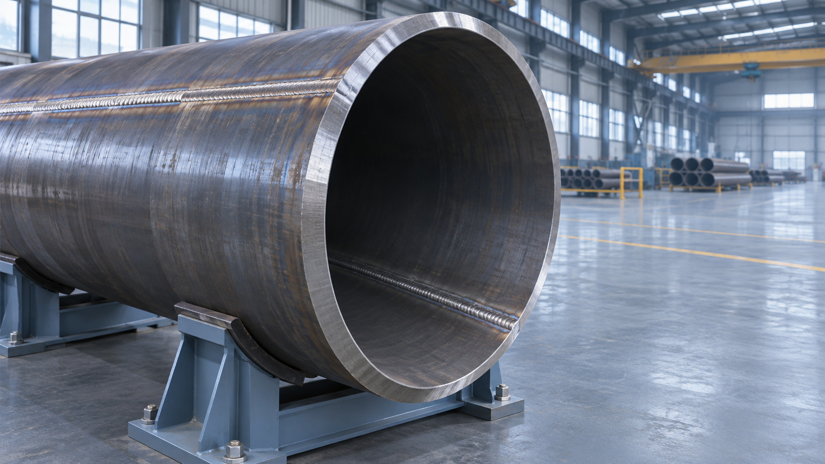
- Double Submerged Arc Welded Pipe: What to Check Before OrderingNov 06, 2026

Weekly Insights
Stay ahead with our curated technology reports delivered every Monday.
Questions about pipe blasting or corrosion protection? Leave a message for technical insights from GPIC.
We respect your privacy. Your information is strictly confidential.
Recommended News